Systems, methods and apparatus for pattern matching in procedure development and verification
What is Al technical title?
Al technical title is built by PatSnap Al team. It summarizes the technical point description of the patent document.
a technology of pattern matching and procedure development, applied in the direction of source code generation, instruments, etc., can solve the problems of inapplicability of satellite systems, inability to achieve high dependability of complex systems in general, and inability to fully automate general purpose approaches covering all domains
Active Publication Date: 2011-07-12
NASA
View PDF2 Cites 12 Cited by
Summary
Abstract
Description
Claims
Application Information
AI Technical Summary
This helps you quickly interpret patents by identifying the three key elements:
Problems solved by technology
Method used
Benefits of technology
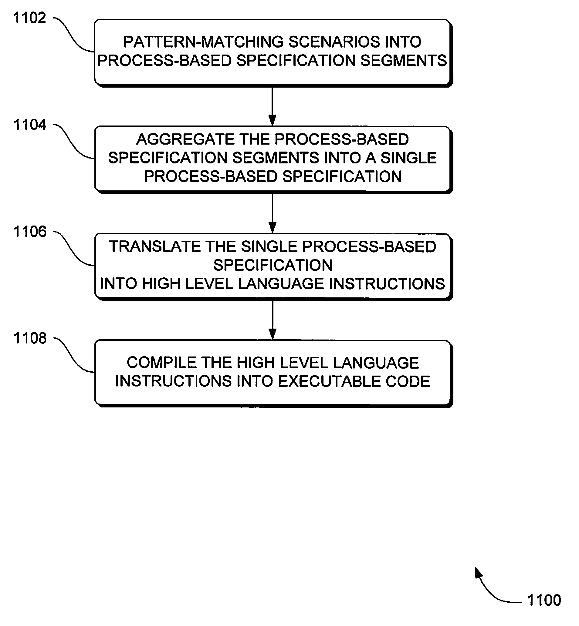
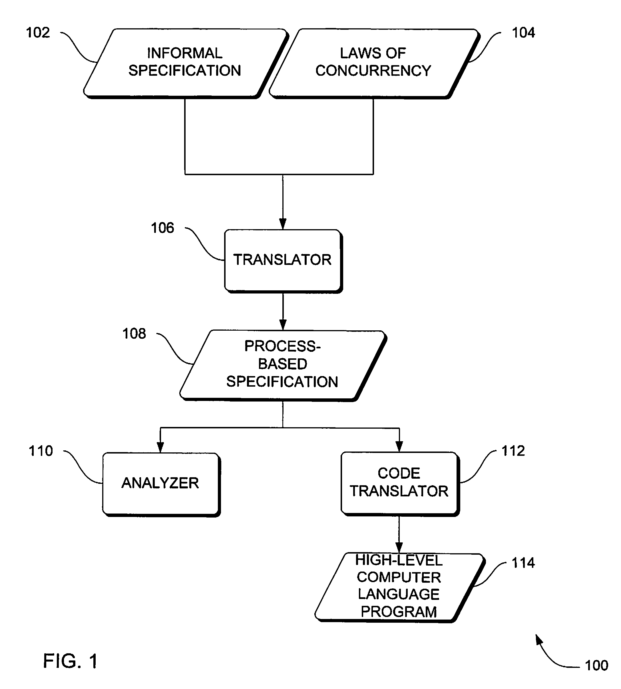
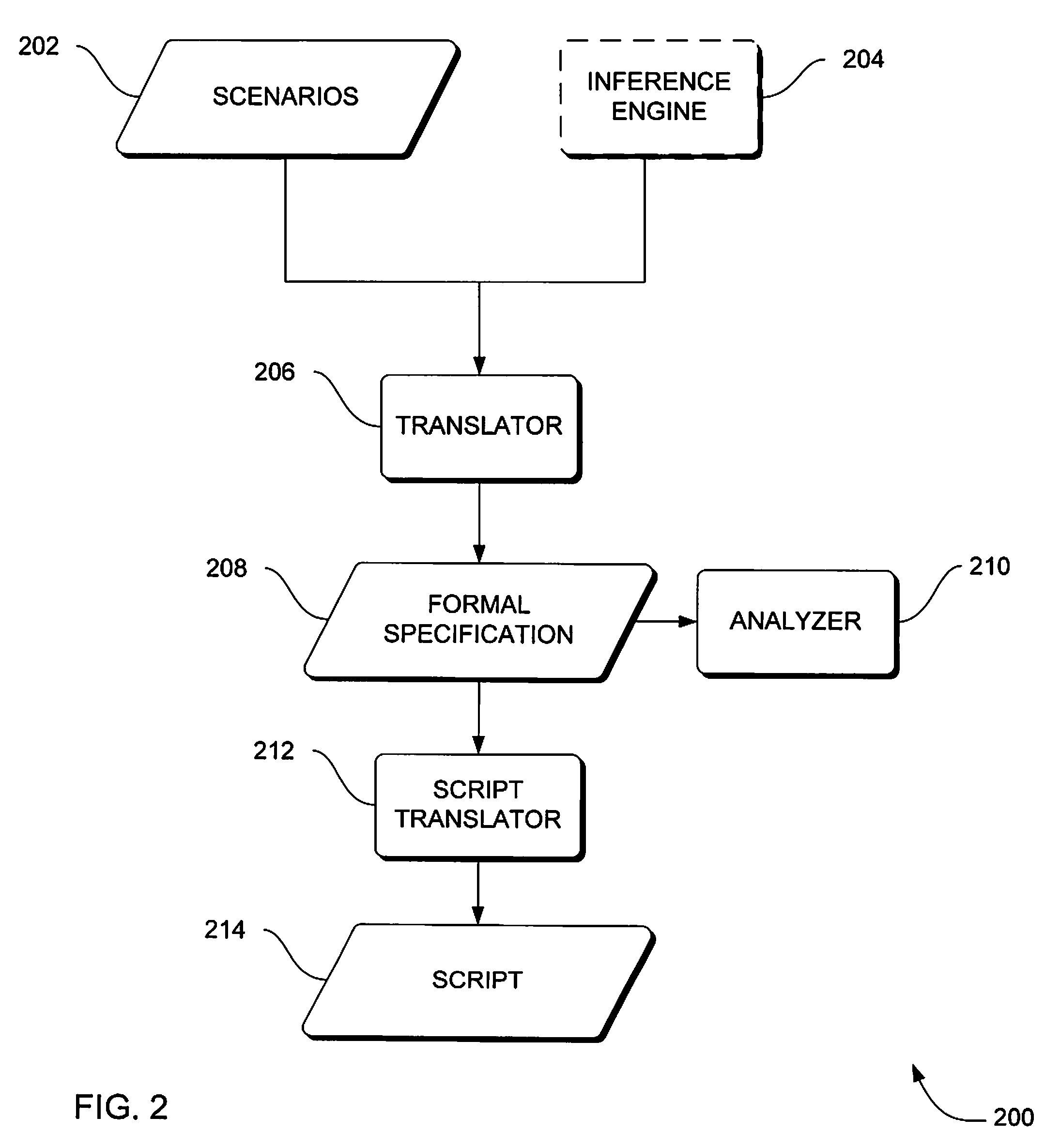
[0015]Some embodiments of the systems, methods and apparatus described herein provide automated analysis, validation, verification, and generation of complex procedures. The generation is performed by pattern matching with set comprehensions without a theorem-prover or a formal proof of correctness. The systems, methods and apparatus may include pattern-matching an equivalent formal model from an informal specification. Such a model can be analyzed for contradictions, conflicts, use of resources before the resources are available, competition for resources, and so forth. From such a formal model, an implementation can be automatically generated in a variety of notations. Some implementations may include traditional programming language code, machine language code, scripts, and / or procedures. The approach can improve the resulting implementation, which, in some embodiments, is provably equivalent to the procedures described at the outset, which in turn can improve confidence that the system reflects the requirements, and in turn reduces system development time and reduces the amount of testing required of a new system. Moreover, in some embodiments, two or more implementations can be “reversed” to appropriate formal models, the models can be combined, and the resulting combination checked for conflicts. Then, the combined, error-free model can be used to generate a new (single) implementation that combines the functionality of the original separate implementations, and may be more likely to be correct.
Problems solved by technology
Complex systems in general cannot attain high dependability without addressing crucial remaining open issues of software dependability.
Some of these actions may be explicit and required, while others can be due to errors arising, or as a result of adapting to changing conditions as the system executes.
A fully automated general purpose approach covering all domains is technically prohibitive to implement in a way that is both complete and consistent.
For example, scenarios for satellite systems might not be applicable as scenarios for systems that manufacture agricultural chemicals.
Validation of the generated code is sometimes performed through the use of a domain simulator, a very elaborate and costly approach that is computationally intensive.
This process of validation via simulation rarely results in an unambiguous result and rarely results in uncontested results among systems analysts.
This approach can be very expensive and exhibit severely limited effectiveness.
In some complex systems, this approach leaves vast parts of possible execution paths forever unexplored and unverified.
Manual change to the system creates a risk of introducing new errors and necessitates retesting and revalidation, which can greatly increase the cost of the system.
Often, needed changes are not made due to the cost of verifying / validating consequential changes in the rest of the system.
Sometimes, changes are simply made in the code and not reflected in the specification or design, due to the cost or due to the fact that those who generated the original specification or design are no longer available.
Method used
Image
Click on the blue label to locate the original text in one second.
Reading with bidirectional positioning of images and text.
Examples
Embodiment Construction
[0045]In the following detailed description, reference is made to the accompanying drawings that form a part hereof, and in which is shown, by way of illustration, specific embodiments which can be practiced. These embodiments are described in sufficient detail to enable those skilled in the art to practice the embodiments, and it is to be understood that other embodiments can be utilized and that logical, mechanical, electrical and other changes can be made without departing from the scope of the embodiments. The following detailed description is, therefore, not to be taken in a limiting sense.
[0046]The detailed description is divided into six sections. In the first section, embodiments of a system level overview are described. In the second section, embodiments of methods are described. In the third section, embodiments of the hardware and the operating environment, in conjunction with which embodiments can be practiced, is described. In the fourth section, particular CSP implemen...
PUM
Abstract
Systems, methods and apparatus are provided through which, in some embodiments, a formal specification is pattern-matched from scenarios, the formal specification is analyzed, and flaws in the formal specification are corrected. The systems, methods and apparatus may include pattern-matching an equivalent formal model from an informal specification. Such a model can be analyzed for contradictions, conflicts, use of resources before the resources are available, competition for resources, and so forth. From such a formal model, an implementation can be automatically generated in a variety of notations. The approach can improve the resulting implementation, which, in some embodiments, is provably equivalent to the procedures described at the outset, which in turn can improve confidence that the system reflects the requirements, and in turn reduces system development time and reduces the amount of testing required of a new system. Moreover, in some embodiments, two or more implementations can be “reversed” to appropriate formal models, the models can be combined, and the resulting combination checked for conflicts. Then, the combined, error-free model can be used to generate a new (single) implementation that combines the functionality of the original separate implementations, and may be more likely to be correct.
Description
RELATED APPLICATIONS[0001]This application is a continuation-in-part of co-pending U.S. application Ser. No. 11 / 461,669 filed on Aug. 1, 2006 entitled “Systems, Methods and Apparatus for Procedure Development and Verification,” which is a continuation-in-part of U.S. application Ser. No. 11 / 203,590 filed Aug. 12, 2005 now U.S. Pat. No. 7,739,671 entitled “Systems, Methods & Apparatus For Implementation Of Formal Specifications Derived From Informal Requirements,” which is a continuation-in-part of U.S. application Ser. No. 10 / 533,376 filed Apr. 29, 2005 now U.S. Pat. No. 7,484,688 entitled “System and Method for Deriving a Process-based Specification.”ORIGIN OF THE INVENTION[0002]The invention described herein was made by employees of the United States Government and may be manufactured and used by or for the Government of the United States of America for governmental purposes without the payment of any royalties thereon or therefor.FIELD OF THE INVENTION[0003]This invention relates...
Claims
Application Information
Patent Timeline
Application Date:The date an application was filed.
Publication Date:The date a patent or application was officially published.
First Publication Date:The earliest publication date of a patent with the same application number.
Issue Date:Publication date of the patent grant document.
PCT Entry Date:The Entry date of PCT National Phase.
Estimated Expiry Date:The statutory expiry date of a patent right according to the Patent Law, and it is the longest term of protection that the patent right can achieve without the termination of the patent right due to other reasons(Term extension factor has been taken into account ).
Invalid Date:Actual expiry date is based on effective date or publication date of legal transaction data of invalid patent.
Patent Type & Authority Patents(United States)
IPC IPC(8): G06F9/44G06F9/45
CPCG06F8/10G06F8/30G06F8/74
Inventor HINCHEY, MICHAEL G.RASH, JAMES L.ROUFF, CHRISTOPHER A.