
Method and apparatus for hierarchical Z buffering and stenciling

a hierarchical z and stenciling technology, applied in the field of graphics rendering, can solve the problems of affecting the efficiency of the video graphics circuit, and increasing the number of unnecessary calculations

Active Publication Date: 2011-07-12
ATI TECH INC
View PDF34 Cites 14 Cited by
  • Summary
  • Abstract
  • Description
  • Claims
  • Application Information

AI Technical Summary

Benefits of technology

The invention is a video graphics system that combines hierarchical z-buffering and stencil operations to efficiently render a plurality of pixels. This helps to improve the efficiency of the video graphics circuit and reduces the unnecessary calculations and pixel information. The invention also includes a method for performing a hierarchical stencil test to determine which pixels will be visible and which ones will be hidden. Overall, the invention allows for more efficient and effective video graphics processing.

Problems solved by technology

Thus, the calculation of such pixel information was unnecessary and adversely affects the efficiency of the video graphics circuit.
If, however, the object has a substantially overlapped portion, then the number of unnecessary calculations increases and the efficiency of the video graphics circuit is affected.
Another inefficiency arises when a stencil is placed on an output image, whereupon all pixels having a location within the stencil are not visible.
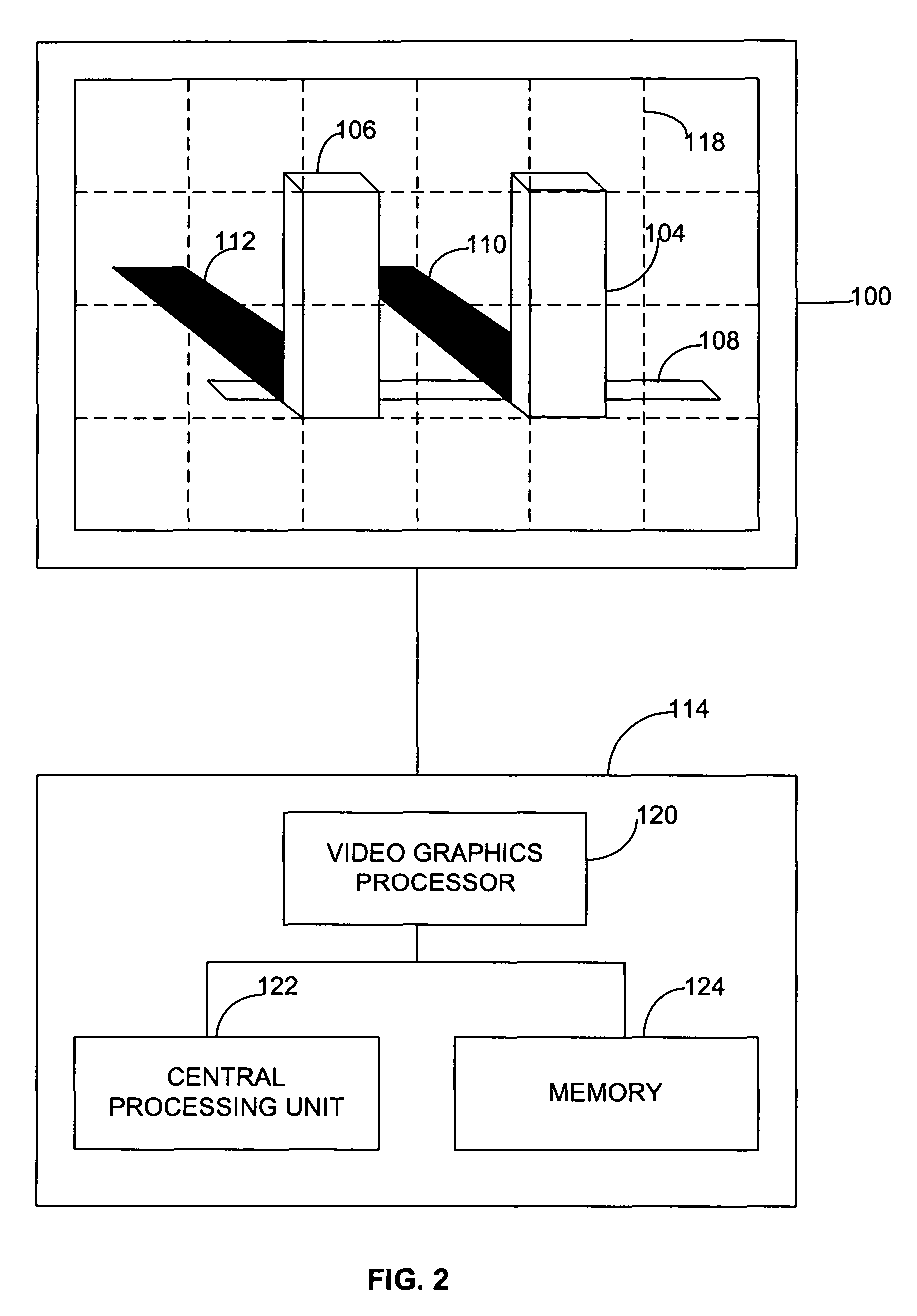
A typical stencil display is a shadow based on the position of a light source, wherein pixels that fall within the shadow are not visible and therefore may be unnecessarily rendered.
Therefore, since the stencil blocks out all pixels at the same x,y address that have a smaller z address than the stencil, i.e. hidden by the shadow, it is inefficient to render the pixels which are not visible by the shadow.
Although, conventional video graphics circuits cannot perform both hierarchical z-buffering and stencil operations because the circuit must choose to perform either the hierarchical z-buffering or the stenciling.
Therefore, without a means of performing a hierarchical stencil test, it is in general impossible to know the correct result for a hierarchical depth test.

Method used


Image

  • Method and apparatus for hierarchical Z buffering and stenciling
  • Method and apparatus for hierarchical Z buffering and stenciling
  • Method and apparatus for hierarchical Z buffering and stenciling

Examples


Embodiment Construction

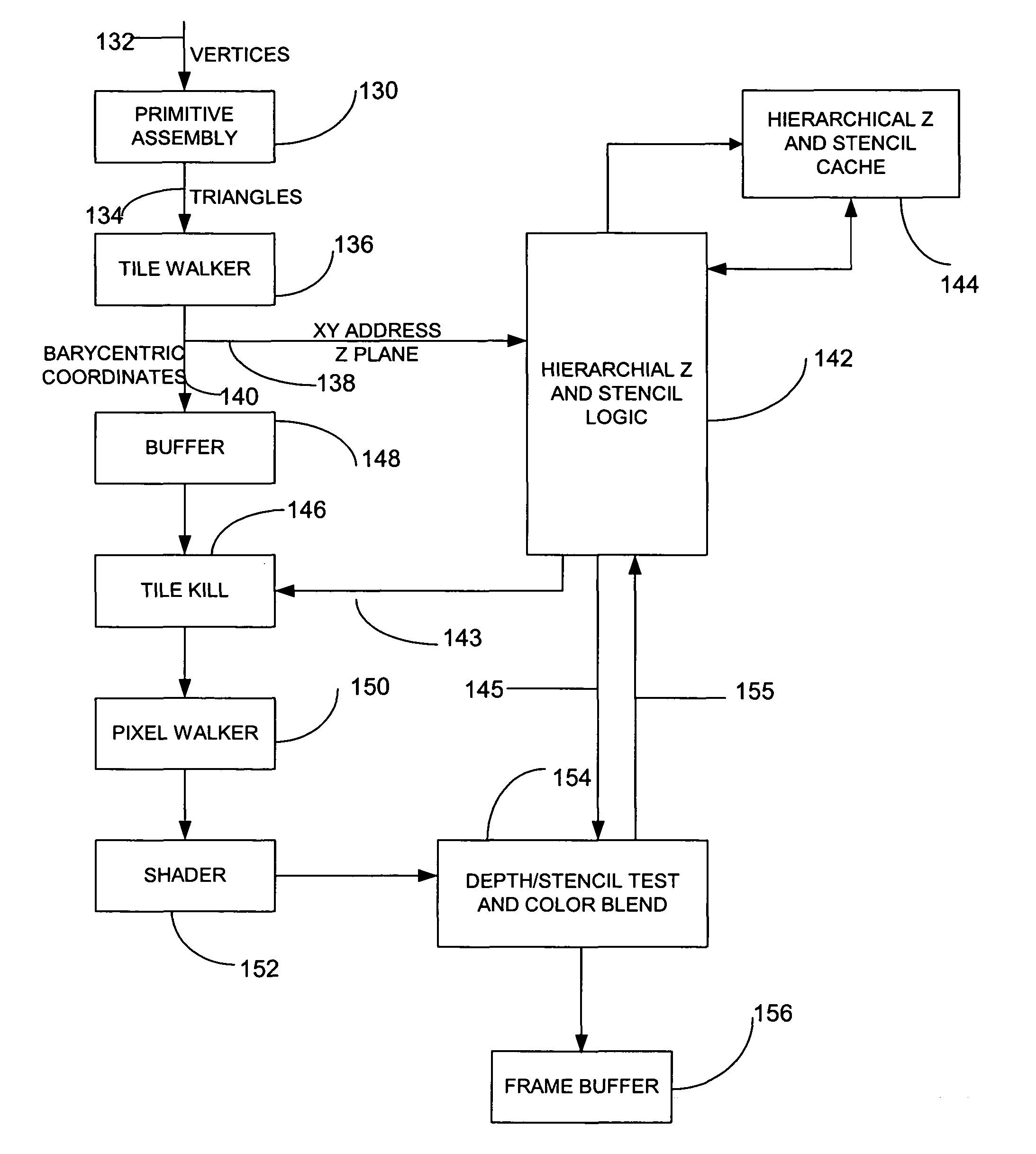
[0022]The disclosed invention includes a method and apparatus for hierarchical Z buffering and stenciling that compares an input tile Z value range with a hierarchical Z value range and a stencil code. The method and apparatus also updates the hierarchical Z value range and stencil code in response to the comparison and determines whether to render a plurality of pixels within the input tile based on the comparison of the input tile Z value range with the hierarchical Z value range and stencil code. In determining whether to render the plurality of pixels within the tile, two different tests are performed, a stencil test and a hierarchical Z value test, otherwise known as a depth test. If the stencil test fails or the hierarchical Z value test fails, a determination is made to not render the pixels, otherwise referred to a killing the tile, as it is determined that the pixels are not visible in the graphical output. It should be noted that the stencil values may need to be changed, ...


PUM


Abstract

A method and apparatus for hierarchical Z buffering stenciling includes comparing an input tile Z value range with a hierarchical Z value range and a stencil code. The method and apparatus also updates the hierarchical Z value range and stencil code in response the comparison and determines whether to render a plurality of pixels within the input tile based on the comparison of the input tile Z value range with the hierarchical Z value range and stencil code. In determining whether to render the tile, a stencil test and a hierarchical Z value test is performed. If one of the test fails, the tile is killed as it is determined that the pixels are not visible in the graphical output. If the stencil test passes and the hierarchical Z test passes, the pixels within the tile are rendered, as it is determined that the pixels may be visible.

Description

FIELD OF THE INVENTION[0001]The invention relates generally to graphics rendering and more particularly to comparing pixel values prior to graphics rendering.BACKGROUND OF THE INVENTION[0002]Video graphics circuits generate pixel information for objects to be displayed on a computer screen, monitor or television. The source for the object may be television broadcasts, cable television transmissions, satellite television transmissions, computer programs, web pages, and so on. For computer screens, video graphic circuits partition each of the objects to be displayed into triangles. Each triangle is stored as three vertexes and corresponding display parameters for each vertex. The corresponding display parameters include color parameters (red, green, blue), display or pixel locations parameters (x, y, z) and texture parameters (s, t, w).[0003]For corresponding display parameters, a video graphics circuit calculates slopes and associated display parameters for each part within the trian...

Claims


Application Information

Patent Timeline
Patent Type & Authority Patents(United States)
IPC IPC(8): G06T15/40G06T15/50G06T1/00G09G5/02
CPCG06T15/405
Inventor SEILER, LARRY D.MOREIN, STEPHEN L.
Owner ATI TECH INC
Learn More