Eureka AIR delivers breakthrough ideas for toughest innovation challenges, trusted by R&D personnel around the world.

Magnet switch with magnetic core designed to ensure stability in operation thereof

a technology of magnetic core and magnet switch, applied in the field of magnet switch, can solve the problems of increasing workability, trouble, and requiring upskilling workers, and achieve the effect of ensuring joint stability

Inactive Publication Date: 2011-07-12
DENSO CORP
View PDF34 Cites 15 Cited by
  • Summary
  • Abstract
  • Description
  • Claims
  • Application Information

AI Technical Summary

Benefits of technology

[0012]It is another object of the invention to provide an improved structure of a magnet switch designed to have enhanced resistance to the impact without complicating production processes thereof and / or ensure the stability of joint between a disc assembly and a core body of a stationary magnetic core.
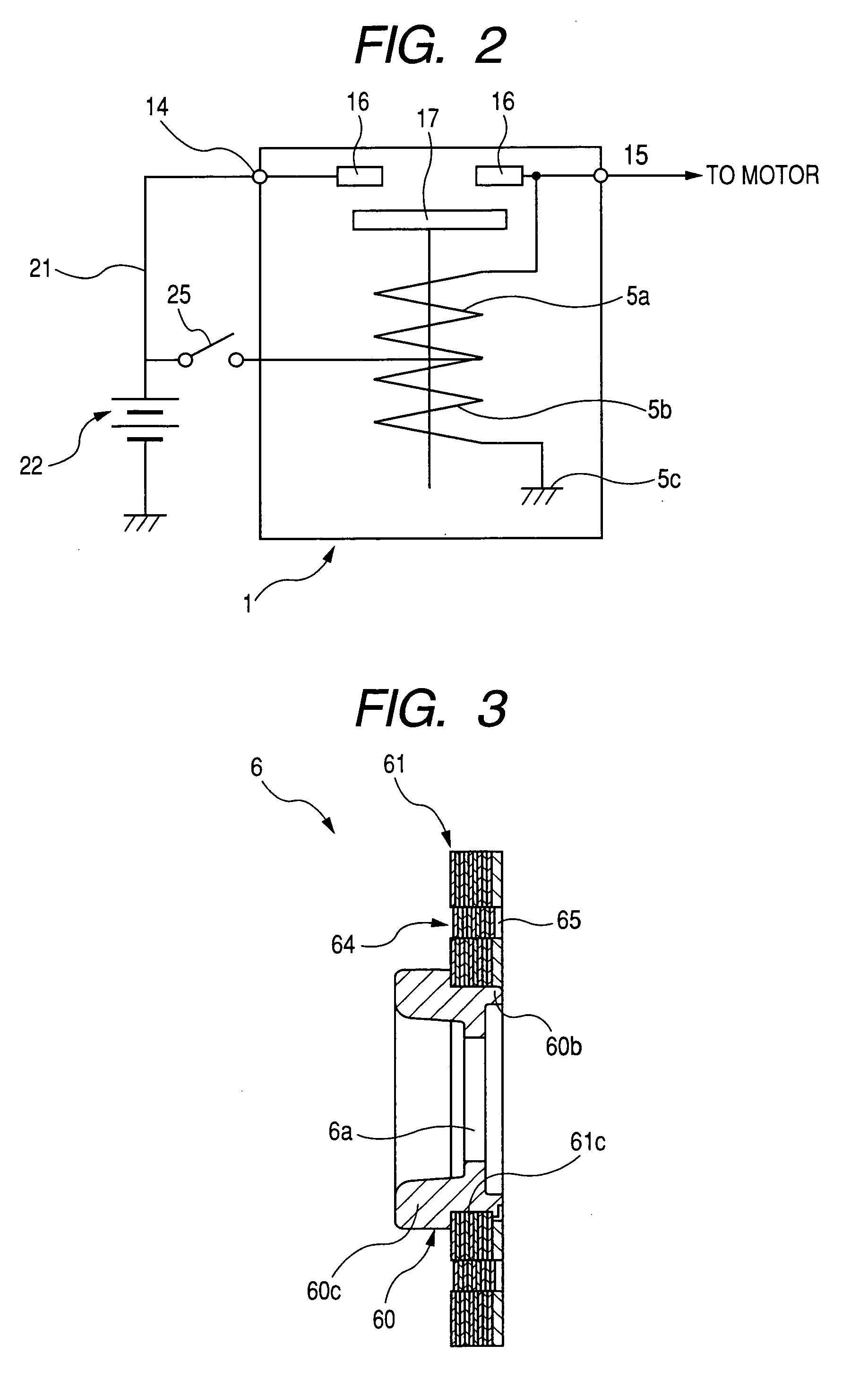
[0042]The stationary core includes a disc assembly and a core body, the core body having opposed ends, a base, a boss, and an outer shoulder formed between the base and the boss. The base has an end that is one of the opposed ends which faces the stationary core. The boss has an end that is the other of the opposed ends which is located away from the movable core across the base. The disc assembly is made of a stack of annular plate members superposed on each other in a thickness-wise direction thereof and has a fitting hole extending through a thickness of the stack. Each of the annular plate members has a circular center hole which defines the fitting hole of the disc assembly. The disc assembly is fit at the fitting hole on the boss. An outermost one of the annular plate members of the disc assembly which is located far away from the base has a chamfered surface formed on an inner circumferential edge of the center hole thereof. An least a portion of an edge of the end of the boss is plastically deformed outward in a radius direction of the boss, so that the plastically deformed portion of the edge is in abutment with the chamfered surface of the outermost one of the annular plate members, thereby creating an elastic nip which retains the stack of the annular plate members of the disc assembly between the plastically deformed portion of the edge and the outer shoulder of the core body. This ensures the stability of joint between the disc assembly and the core body even when the center holes of the plate members vary in inner diameter, have distortions, or lack in sheared area thereof.

Problems solved by technology

This is, however, very troublesome and requires upskilling workers.
Additionally, the tab 400 formed on the outermost one of the sheets of the disc assembly 110 obstructs soldering of the end of the coil to the disc assembly 110, thus resulting in a decrease in workability.
This results in an increase in total production const of the magnet switch.

Method used


Image

  • Magnet switch with magnetic core designed to ensure stability in operation thereof
  • Magnet switch with magnetic core designed to ensure stability in operation thereof
  • Magnet switch with magnetic core designed to ensure stability in operation thereof

Examples


first embodiment

[0068]Referring to the drawings, wherein like reference numbers refer to like parts in several views, particularly to FIG. 1, there is shown a direct-acting magnet switch 1 for engine starters according to the invention. The magnet switch 1 is designed to open or close main contacts, as will be described later in detail, installed in a motor energizing circuit, as will also be referred to as a motor circuit below, to turn on an electric motor of the engine starter to start automotive internal combustion engines. The magnet switch 1 includes a solenoid assembly 2 serving as an electromagnet and a switch cover 3 joined to the solenoid assembly 2.

[0069]The solenoid assembly 2 consists of a switch casing 4 serving as a yoke, a magnetic coil 5 disposed inside the switch casing 4, a stationary magnetic core 6 to be magnetized upon excitation of the coil 5, a plunger 8 functioning as a movable core disposed slidably inside the coil 5, and a shaft (also called a plunger rod) 9 disposed to b...

second embodiment

[0094]FIG. 8 illustrates the disc assembly 61 according to the invention.

[0095]The disc assembly 61 is made up only of a stack of nine (9) annular sheets 61a which are identical in structure with the ones in the first embodiment illustrated in FIGS. 1 to 7. The rubber gasket 13 has a center hole 250 in which the end of the small-diameter portion 60b is disposed. The rubber gasket 13 also has arc-shaped recesses 132 and holes 131 formed therein. The arc-shaped recesses 132 are identical in structure and intended use with the arc-shaped recesses 62 of the annular plate 61b of the disc assembly 6 of the first embodiment. Similarly, the holes 131 are identical in structure and intended use with the holes 65 of the disc assembly 6 of the first embodiment. The holes 131 have the diameter great enough to avoid physical interference with the embossed protrusions 64 of the sheets 61a. The protrusions 64 and the tabs 60c are located not to obstruct the operations of switching parts such as th...

third embodiment

[0096]FIGS. 9, 10(a), and 10(b) illustrate the magnetic core 6 according to the invention.

[0097]The disc assembly 61 is, like in the first embodiment, made up of a stack of nine (9) sheets 61a and a plate 61b which are superposed on one another in the axial direction of the magnetic core 6. The thickness of the plate 61b is two to five times, preferably three to four times that of the sheets 61b. This results in a mechanical property balance between the elasticity and the rigidity of the plate 61b.

[0098]Each of the sheets 61a, like in the first embodiment, has two embossed protrusions 64 (only one is shown in FIG. 9 for the brevity of illustration). Each of the protrusions 64, unlike in the first embodiment, projects away from the movable contact 17 (i.e., the left direction, as viewed in the drawing). The protrusions 64 of each of the sheets 61a are press-fit in those of the adjacent one in alignment to hold the sheets 61a from rotating in the circumferential direction thereof. Si...


PUM

PropertyMeasurementUnit
magnetic attractionaaaaaaaaaa
thicknessaaaaaaaaaa
elasticaaaaaaaaaa

Abstract

A magnet switch which may be employed in automotive engine starters is provided. The magnet switch includes a stationary magnetic core made up of a disc assembly and a core body. The disc assembly is made of a stack of annular plate members superposed on each other. Each of the plate members has an opening through which a terminal lead of a magnetic coil extends. The core body has a boss with an edge which is plastically deformed outwardly in the radius direction thereof or staked to create an elastic nip which retains the stack of the plate members firmly on the core body. This structure ensures the joint between the disc assembly and the core body to withstand mechanical impact exerted on the magnetic core and stability in operation of the magnet switch without increasing a total production cost of the magnetic switch.

Description

CROSS REFERENCE TO RELATED DOCUMENT[0001]The present application claims the benefit of Japanese Patent Application Nos. 2007-206266 filed on Aug. 8, 2007, 2007-293545 filed on Nov. 12, 2007, and 2008-149173 filed on Jun. 6, 2008, the disclosure of which is incorporated herein by reference.BACKGROUND OF THE INVENTION[0002]1. Technical Field of the Invention[0003]The present invention relates generally to a magnet switch which may be employed in an engine starter working to start an internal combustion engine of automotive vehicles, and more particularly to an improved structure of such a magnet switch designed to have improved resistance to impact shock occurring during operation of the magnet switch without increasing production costs.[0004]2. Background Art[0005]Japanese translation No. 2002-524826 of a PCT internal patent application teaches a magnet switch which is, as illustrated in FIG. 20, equipped with a disc assembly made 110 of a stack of annular sheets 111 and a cylindrica...

Claims


Application Information

Patent Timeline
Patent Type & Authority Patents(United States)
IPC IPC(8): H01H67/02H01F3/00H01F7/08
CPCH01F3/02H01H51/065Y10T29/49009H01F7/081
Inventor USAMI, SHINJITERAMACHI, TOMOHIRO
Owner DENSO CORP
Why Eureka
Eureka Blog
Learn More