
Protective relay and human-machine interface therefor

a protection relay and human-machine interface technology, applied in relays, circuit-breaking switches, instruments, etc., can solve the problems of 40° msec delay delay of protection relays to release trip signals, and inability of auxiliary-powered protection relays to be acceptable, and achieve the effect of higher resolution

Active Publication Date: 2011-07-05
ABB (SCHWEIZ) AG
View PDF8 Cites 4 Cited by
  • Summary
  • Abstract
  • Description
  • Claims
  • Application Information

AI Technical Summary

Benefits of technology

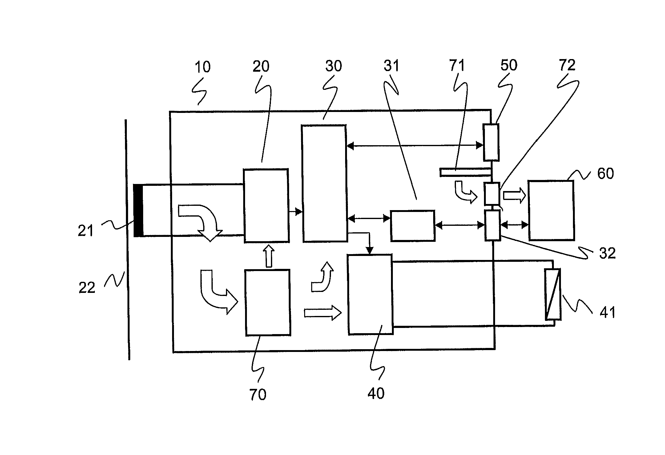
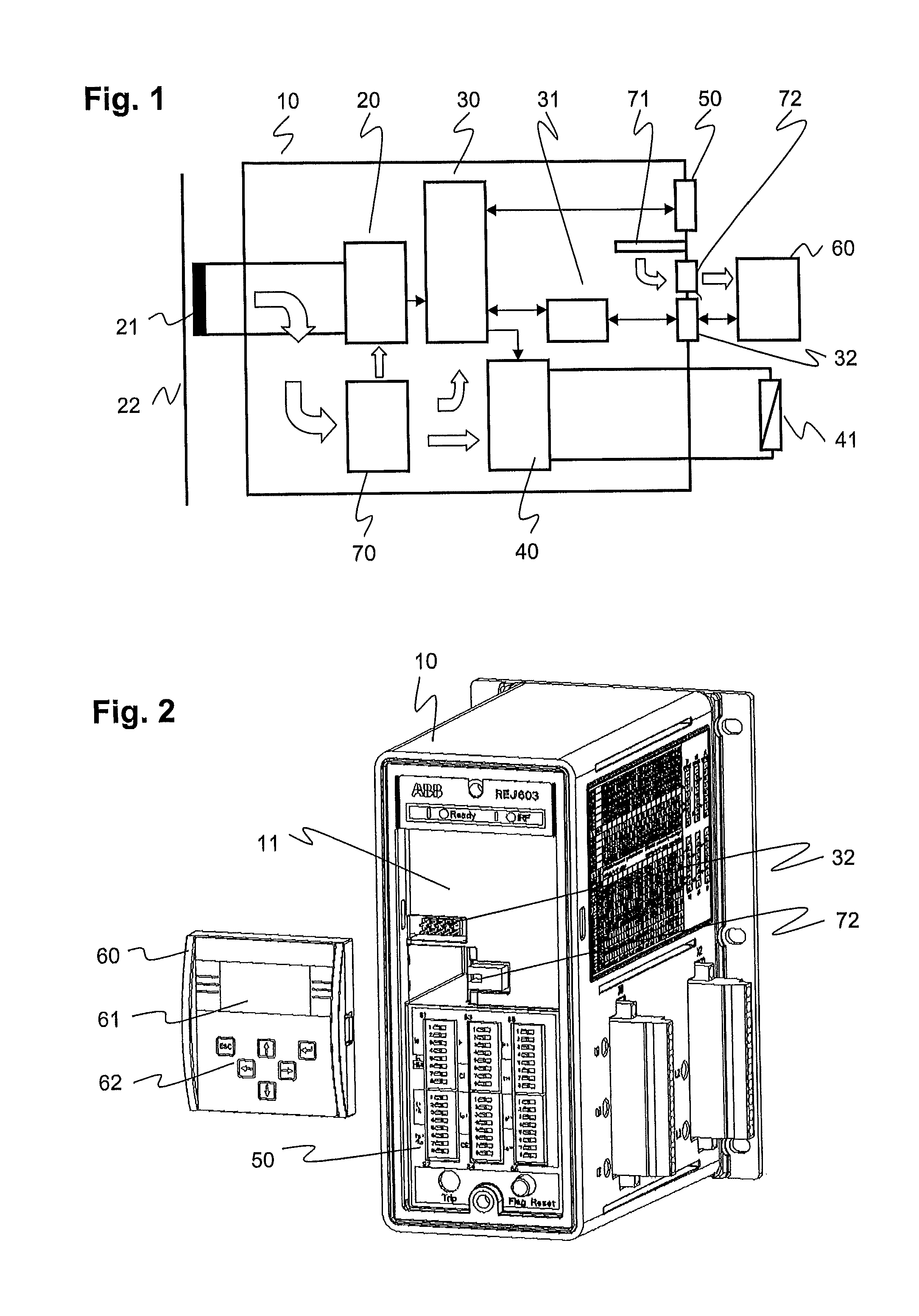
The present patent provides a protective relay for protecting electrical equipment in a power distribution system. The relay has an input module to receive a signal about the condition of a medium voltage power line, a processing module to digitally process the signal, and an output module to supply energy to an actuator of a circuit breaker. The relay also has a detachable human machine interface (HMI) with input components to set the operating parameters of the relay, and an interface to exchange data between the processing module and the detachable HMI. The relay also has a base HMI with mechanical switches to set the operating parameters, and the processing module receives a fine setting of the operating parameters from the detachable HMI. The technical effect of this invention is to provide a protective relay with advanced features and capabilities to protect electrical equipment in a power distribution system.

Problems solved by technology

For instance, fault currents above twenty times the rated current of a current transformer may cause the protection relay to release a trip signal with 40° msec delay.
However, in certain situations such as Ring Main Units (RMU) installations in urban areas, auxiliary-powered protection relays may not be acceptable, and so-called self-powered or self-supplied relays are used instead.

Method used


Image

  • Protective relay and human-machine interface therefor
  • Protective relay and human-machine interface therefor

Examples


Embodiment Construction

[0012]Exemplary embodiments of the present disclosure provide a protective relay having an increased flexibility of use.

[0013]An exemplary embodiment of the present disclosure provides a fully operational digital protective relay or Intelligent Electronic Device (IED) for protecting electrical equipment by tripping a circuit breaker and interrupting a power line. The exemplary protective relay or IED includes an input module, a processing module and an output module. Signals received from current transformers connected to the input module are evaluated by the processing module, and in reaction thereto, trip signals can be output to an actuator of the circuit breaker via the output module. A base Human Machine Interface (HMI) enables a user to enter operating parameters such as delay time or nominal current to the processing module. Optionally, a further HMI may be attached to the protective relay and connected, via a suitable interface for data exchange, to the processing module. Th...


PUM


Abstract

A fully operational digital protective relay or Intelligent Electronic Device (IED) are provided for protecting electrical equipment of a power distribution system. The relay includes an input module, a processing module and an output module. Signals received from current transformers connected to the input module are evaluated by the processing module, and in reaction thereto, trip signals can be output to an actuator of a circuit breaker via the output module. A base Human Machine Interface (HMI) enables a user to enter operating parameters such as a delay time or nominal current to the processing module. Optionally, a further HMI may be attached to the protective relay and connected, via a suitable interface for data exchange, to the processing module for the purpose of displaying protection-related information to a user. This further HMI is both optional and detachable. For example, the further HMI can be repeatedly attached to and detached from the protection device. The detachable HMI provides for an increased flexibility in the use of the protective relay, as a user may adapt its interfacing capability by acquiring a detachable HMI of the type and at the time that best suits his evolving needs.

Description

RELATED APPLICATIONS[0001]This application claims priority as a continuation application under 35 U.S.C. §120 to PCT / EP2008 / 065987, which was filed as an International Application on Nov. 21, 2008 designating the U.S., and which claims priority to European Application 07122389.5 filed in Europe on Dec. 5, 2007. The entire contents of these applications are hereby incorporated by reference in their entireties.FIELD[0002]The present disclosure relates to the field of electrical power distribution. More particularly, the present disclosure relates to a protective relay for protecting electrical equipment in a power distribution system.BACKGROUND INFORMATION[0003]A power distribution system is the interface between the power transmission network and the electricity end-customers. The power distribution system can include a number of primary substations which are connected to secondary substations via power lines and switches. The primary substations contain transformers that reduce the ...

Claims


Application Information

Patent Timeline
Patent Type & Authority Patents(United States)
IPC IPC(8): H01H47/00
CPCH01H71/123H02H3/006H01H2071/006H01H71/7409
Inventor SHAH, VIJAYDECK, BERNHARD
Owner ABB (SCHWEIZ) AG
Learn More