Eureka AIR delivers breakthrough ideas for toughest innovation challenges, trusted by R&D personnel around the world.

Seat structure

a seat and structure technology, applied in the field of seat structures, can solve the problems of affecting peripheral fatigue, heavy weight of the seat, and insufficient restoring force, and achieve the effects of improving the peripheral fatigue of the sitter, not hindering the biological rhythm of the sitter, and excellent effects

Inactive Publication Date: 2011-07-05
DELTA TOOLING CO LTD
View PDF33 Cites 32 Cited by
  • Summary
  • Abstract
  • Description
  • Claims
  • Application Information

AI Technical Summary

Benefits of technology

[0043]A seat structure relating to the present invention as described above has excellent effects in being capable of absorbing whole-body vibrations and impact vibrations, not hindering the biological rhythms of a sitter and therefore ameliorating peripheral fatigue of the sitter accompanying a long period of sitting, and moderating impact forces by ease of movement to rearward of the body at a time of impact and control of attenuation ratios of a seat back and seat cushion which suppress rebounding.

Problems solved by technology

However, with such structures, there have been problems in that the restoring force tends to be insufficient or that the weight thereof is heavy.
Now, the characteristics of body pressure distribution and posture maintenance affect stresses on the sitter which are based on pressure forces, restraint forces and the like that act on the sitter, and these stresses principally affect peripheral fatigue.
On the other hand, vibration absorption characteristics have an influence on stress based on the acceleration of vibrations transmitted to the sitter, and this stress principally affects peripheral fatigue in conditions when the whole body is exposed to vibrations.
Further, peripheral fatigue of a sitter is ameliorated by fluctuating movements.

Method used


Image

  • Seat structure
  • Seat structure
  • Seat structure

Examples


Embodiment Construction

Problem to be Solved by the Invention

[0012]In consideration of the circumstances described above, an object of the present invention is to provide a seat structure which can ameliorate peripheral fatigue of a sitter that accompanies a long period of sitting.

Means for Solving the Problem

[0013]A seat structure relating to a first aspect of the present invention is a seat structure provided with: a sitting portion frame; and a cushion material including a sheet material, of which a front edge side is fixed at a front edge side of the sitting portion frame and a back edge side is connected to a back edge side of the sitting portion frame via a resilient member, the cushion material including spring characteristics in which, in a stationary sitting state, a spring constant of a portion that supports a protrusion portion of a sitter is smaller than a spring constant of another portion.

[0014]At the seat structure relating to the first aspect of the present invention, in a state in which a ...


PUM


Abstract

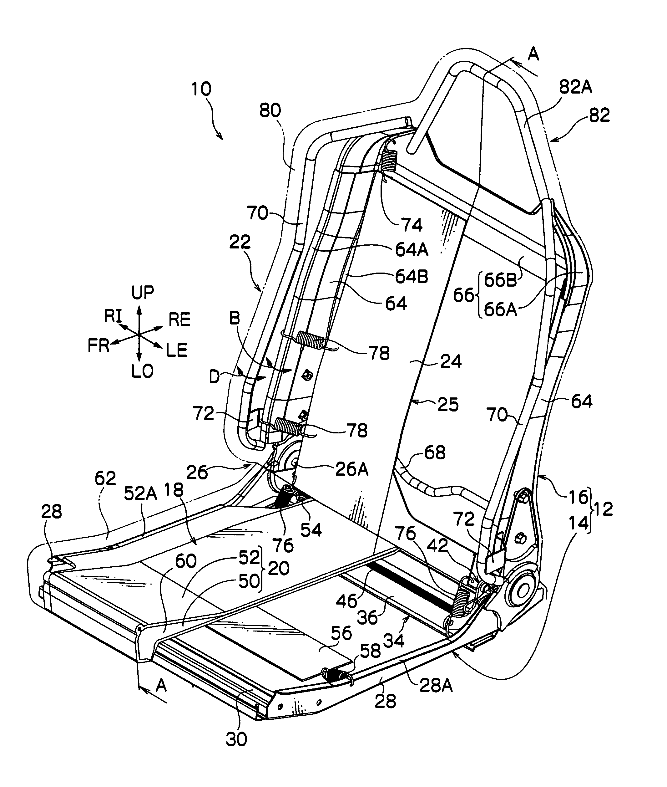
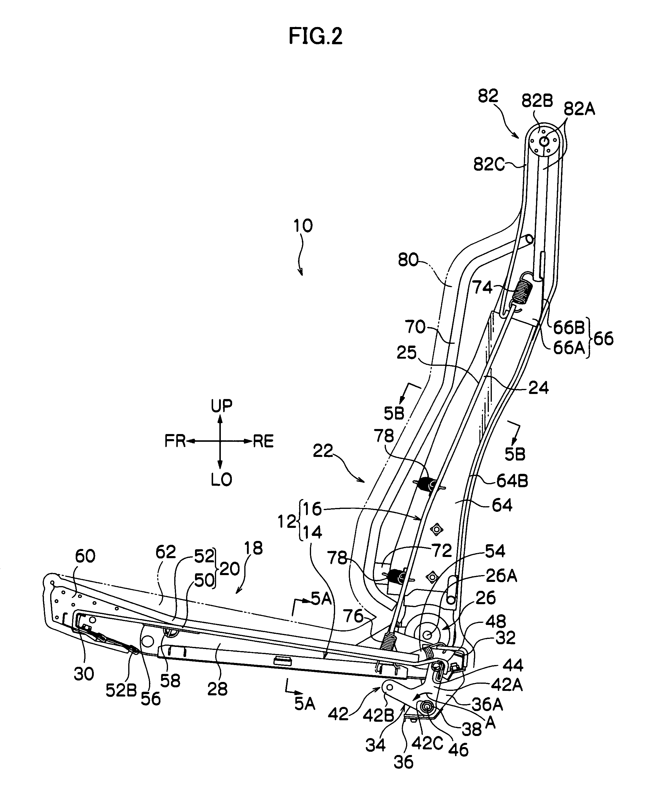
A seat structure which can ameliorate fatigue of a sitting person in accordance with a long period of sitting is provided.In a vehicle seat 10, a back edge side of a lower layer sheet 50 of a cushion material 20, of which a front edge side is fixed to a front edge side of a sitting portion frame 14, is resiliently connected to a back edge side of the sitting portion frame 14 via a movable frame 34 and a torsion bar 46, which is a resilient member. The cushion material 20 has a spring zero characteristic in which a spring constant of a portion that supports a protrusion portion of the sitting person is smaller than a spring constant of other portions. This vehicle seat 10 makes smaller the energy of vibrations which are transmitted to a spinal column portion of the sitting person through the sitting portion frame 14, and peripheral portions thereof convert vibrations corresponding to fluctuations in the body and transmit these through the sitting portion frame 14. α waves of 10 Hz to 12 Hz, which occur in a relaxed waking state, are caused in the brain of the sitting person. Vibrations in a resonance frequency region are attenuated in amplitude and transmitted to the sitting person.

Description

TECHNICAL FIELD[0001]The present invention relates to a seat structure, and particularly relates to a seat structure of a vehicle seat which is mounted at a vehicle such as an automobile or the like.BACKGROUND ART[0002]As a seat for a vehicle, seats which have a cushion material formed of polyurethane foam (below referred to as urethane) have been known. For the cushion structure of such a vehicle seat, a structure has been widely employed in which a cushion material made of urethane is mounted on a spring material, such as Contour Mat (trade name) or the like, or a plate or the like provided at a sitting portion frame, a back portion frame or the like, and these are covered in a fabric material.[0003]Consequently, it has been known that the shape (a design form) and resilience characteristics of the cushion material and compression characteristics of the polyurethane foam greatly affect characteristics of body pressure distribution from a sitter, vibration absorption and suchlike. ...

Claims


Application Information

Patent Timeline
Patent Type & Authority Patents(United States)
IPC IPC(8): B60N2/50A47C7/44A47C7/02A47C7/35B60N2/70B60N2/90
CPCB60N2/70B60N2/7058B60N2/7094
Inventor FUJITA, ETSUNORIOGURA, YUMIUENO, YOSHIYUKI
Owner DELTA TOOLING CO LTD
Why Eureka
Eureka Blog
Learn More