
Dynamic allocation of drive torque

a technology of drive torque and dynamic allocation, which is applied in the direction of electric control, instruments, combustion air/fuel air treatment, etc., can solve the problems of insufficient vacuum, affecting vehicle performance and fuel economy, etc., and achieve accurate allocation of propulsion torque, accurate estimation, and available maximum engine torque

Active Publication Date: 2011-06-28
FORD GLOBAL TECH LLC
View PDF16 Cites 59 Cited by
  • Summary
  • Abstract
  • Description
  • Claims
  • Application Information

AI Technical Summary

Benefits of technology

The patent text describes a method for improving the operation of hybrid vehicles by accurately estimating the maximum engine torque available and adjusting the range of the engine based on the vehicle's operating conditions. This allows for better allocation of propulsion torque among the various sources, resulting in improved vehicle performance and fuel economy. The method can adapt to production variations, engine aging, and other factors that may affect the engine's output.

Problems solved by technology

Such operation can affect vehicle performance and fuel economy.
Further still, if the engine is over-taxed, it may provide insufficient vacuum for various conditions, such as fuel vapor purging.

Method used


Image

  • Dynamic allocation of drive torque
  • Dynamic allocation of drive torque
  • Dynamic allocation of drive torque

Examples


Embodiment Construction

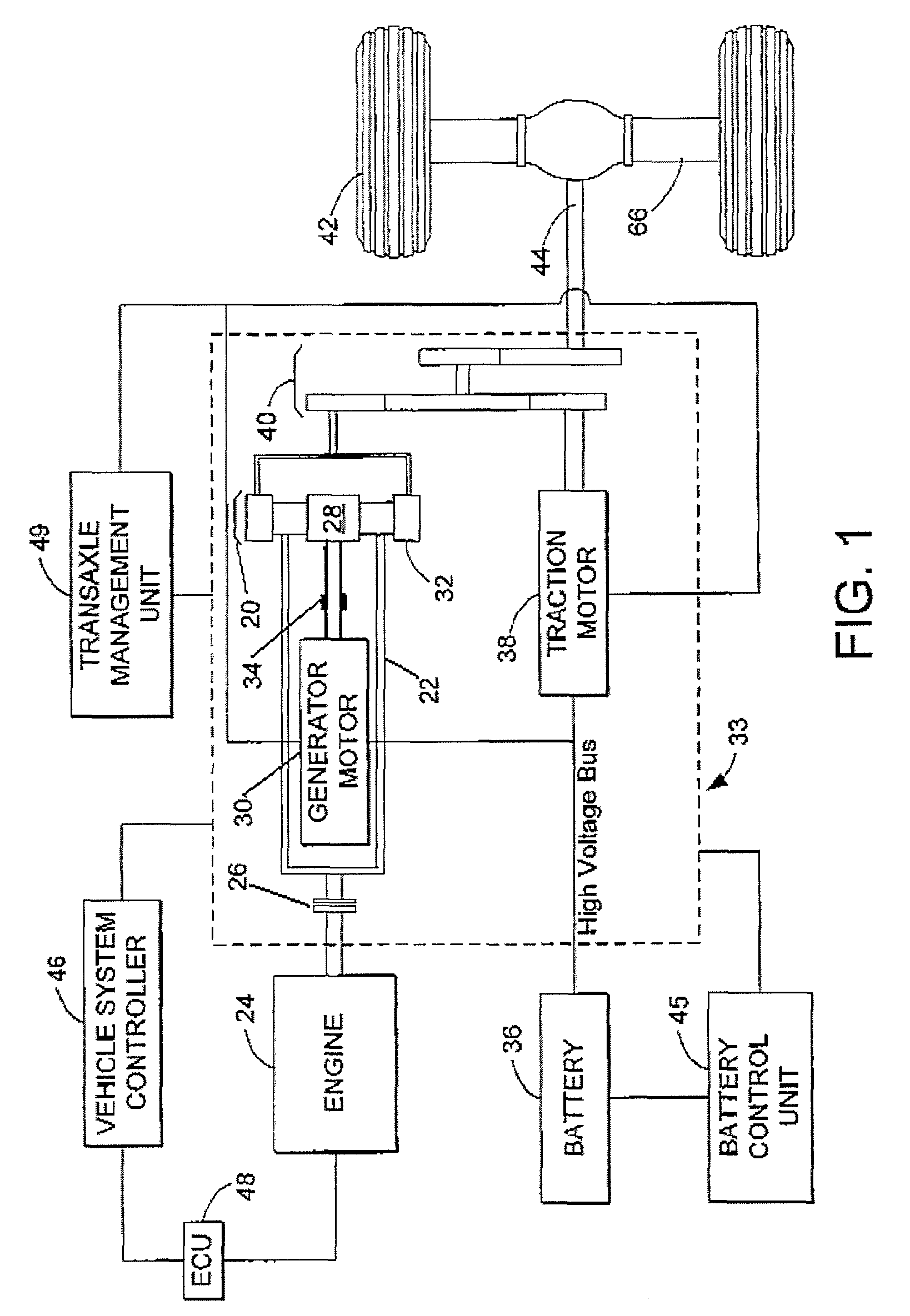
[0012]The present disclosure may be directed to vehicles that include two or more different power sources, such as hybrid electric vehicles (HEVs). FIG. 1 demonstrates one possible configuration, specifically a parallel / series hybrid electric vehicle (split) configuration. However, various other hybrid configurations may be used, such as series, parallel, integrated starter / alternator, etc.

[0013]In an HEV, a planetary gear set 20 mechanically couples a carrier gear 22 to an engine 24 via a one way clutch 26. The planetary gear set 20 also mechanically couples a sun gear 28 to a generator motor 30 and a ring (output) gear 32. The generator motor 30 also mechanically links to a generator brake 34 and is electrically linked to a battery 36. A traction motor 38 is mechanically coupled to the ring gear 32 of the planetary gear set 20 via a second gear set 40 and is electrically linked to the battery 36. The ring gear 32 of the planetary gear set 20 and the traction motor 38 are mechanica...


PUM


Abstract

A method for operating a powertrain in a hybrid vehicle is provided. The method comprises providing torque to drive the vehicle from both an electric drive and an engine, where engine torque is varied within an allowable range. When operating the engine at an edge of the range, the range may be adjusted based on conditions. In this way, it is possible to compensate for an engine that has a variable maximum torque output depending on operating conditions.

Description

BACKGROUND AND SUMMARY[0001]In some vehicles, such as hybrid vehicles, a high level system controller may control a plurality of power and / or torque sources for propelling the vehicle. For example, the controller may allocate a total drive request among the various sources in different ways depending on operating conditions.[0002]In one example, one factor considered by the controller in allocating the request among the various sources is the available output range of an individual source. For example, an engine may have a variable maximum torque output depending on operating conditions, and it may further change as the engine ages. Thus, if the range varies differently from the predicted range, the allocation made by the controller may result in the engine operating at less than its peak output, or providing less output than the controller requests. Such operation can affect vehicle performance and fuel economy. Further still, if the engine is over-taxed, it may provide insufficien...

Claims


Application Information

Patent Timeline
Patent Type & Authority Patents(United States)
IPC IPC(8): B60K1/02
CPCB60K6/365B60K6/445B60W10/06F02D41/1497F02D41/0042B60K1/02B60W20/00Y10T477/68F02D2250/18Y02T10/6239Y10T477/23B60W2710/0666Y02T10/62B60W20/40B60W2710/0622B60W2510/08B60W2510/06B60W10/04
Inventor MARTIN, DOUGLAS RAYMONDBADILLO, EDWARDGARTNER, PAUL M.
Owner FORD GLOBAL TECH LLC
Learn More