Apparatus and method for repairing a core spray line pipe weld joint

a technology of spray line and weld joint, which is applied in the field of weld joints, can solve the problems of affecting the structural integrity affecting the service life of the core spray line,

Active Publication Date: 2011-06-21
GE HITACHI NUCLEAR ENERGY AMERICAS
View PDF27 Cites 3 Cited by
  • Summary
  • Abstract
  • Description
  • Claims
  • Application Information

AI Technical Summary

Benefits of technology

[0005]In an exemplary embodiment, a clamping device supports or structurally replaces a weld joint between connected pipes. The clamping device includes an upper clamp body and a lower clamp body securable on opposite sides of the connected pipes in facing relation, and at least one clamp bolt connecting the upper and lower clamp bodies and extendable through the connected pipes. One of the upper and lower clamp bodies has at least one shaped depression, which receives a complementary shaped clamp bolt nut engageable with the clamp bolt. The shaped depression prevents rotation of the clamp bolt nut.
[0006]In another exemplary embodiment, the clamping device supports or structurally replaces a weld in a core spray line in close proximity to a T-box in a boiling water nuclear reactor. In this context, the clamping device includes an upper clamp body and a lower clamp body securable on opposite sides of the spray line in facing relation. The upper and lower clamp bodies include a trimmed section adjacent the T-box to ensure clearance from the T-box. At least one clamp bolt connects the upper and lower clamp bodies and extends through the spray line. One of the upper and lower clamp bodies has at least one shaped depression, which receives a complementary shaped clamp bolt nut engageable with the clamp bolt. The shaped depression prevents rotation of the clamp bolt nut.
[0007]In yet another exemplary embodiment, a method of supporting or structurally replacing a weld joint between connected pipes includes the steps of forming at least one aperture through the connected pipes in a joint area; securing the upper clamp body and the lower clamp body on opposite sides of the connected pipes in facing relation; connecting the upper and lower clamp bodies by a clamp bolt extendable through at least one aperture and securing the clamp bolt with a clamp bolt nut, the clamp bolt nut having a non-circular shape; and preventing rotation of the clamp bolt nut by engaging the clamp bolt nut in a correspondingly shaped depression in one of the upper and lower clamp bodies.

Problems solved by technology

The welds in the core spray system piping, however, are susceptible to intergranular stress corrosion cracking (IGSCC).
As a consequence, welded pipe joints in the core spray line can become cracked.
In the event that cracking should occur in the P3a weld, the structural integrity of the core spray line, which delivers cooling water to the reactor core, would be lost.

Method used


Image

  • Apparatus and method for repairing a core spray line pipe weld joint
  • Apparatus and method for repairing a core spray line pipe weld joint
  • Apparatus and method for repairing a core spray line pipe weld joint

Examples


Embodiment Construction

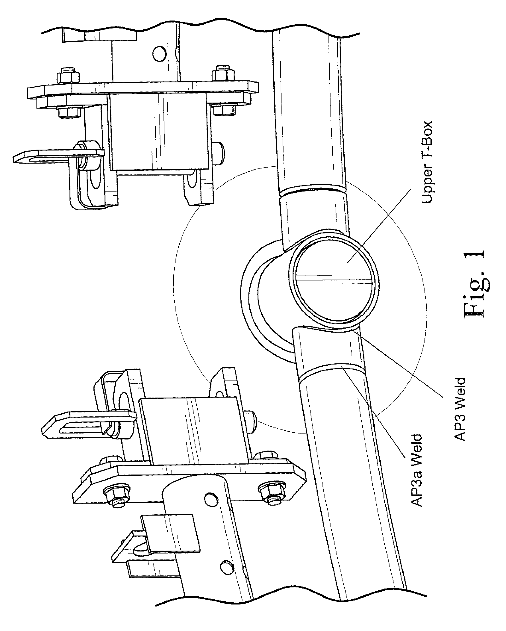
[0015]A clamping device is described herein that structurally supports or replaces a welded connection between connected pipes and, in particular, replaces the P3a weld that joins a short section of horizontal piping to the remainder of the horizontal piping in the core spray line. The clamping device is applicable to reactor plants with varying sized core spray lines.

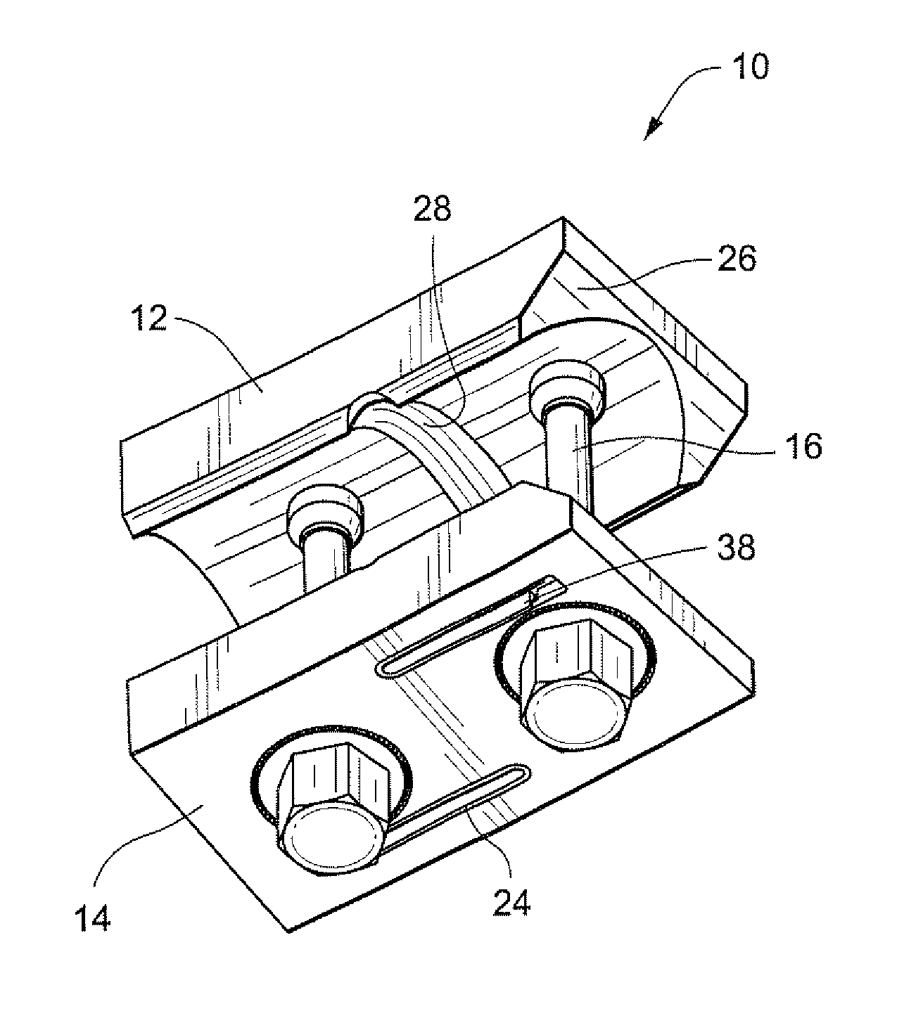
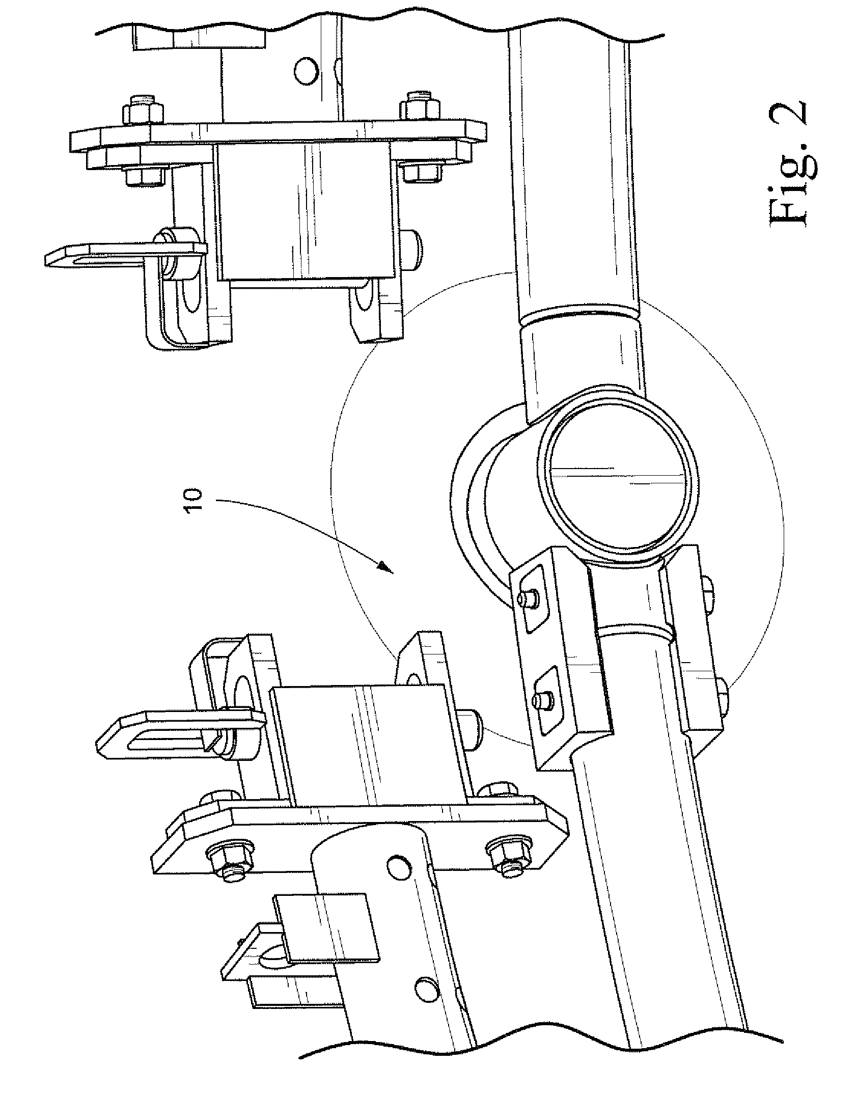
[0016]FIG. 2 shows the clamp assembly 10 installed on the core spray line. FIGS. 3 and 4 are isometric views of the clamp assembly 10. The clamp assembly 10 includes an upper clamp body 12 and a lower clamp body 14, which interface with the core spray line. The clamp bodies 12, 14 are held in position on the horizontal pipe by at least one clamp bolt 16, preferably two, which pass through holes formed in the horizontal pipe. A clamp bolt nut 18 is threaded on an end of each clamp bolt 16.

[0017]The outside diameter of the core spray line can vary within specified manufacturing tolerances. Also, a curved pipe that has be...


PUM


Abstract

A clamping device supports or structurally replaces a weld joint between connected pipes. The clamping device includes an upper clamp body and a lower clamp body securable on opposite sides of the connected pipes in facing relation, and at least one clamp bolt connecting the upper and lower clamp bodies and extendable through the connected pipes. One of the upper and lower clamp bodies has at least one shaped depression, which receives a complementary shaped clamp bolt nut engageable with the clamp bolt. The shaped depression prevents rotation of the clamp bolt nut.

Description

BACKGROUND OF THE INVENTION[0001]The invention relates generally to a weld joint and, more particularly to an apparatus and method for repairing or replacing a core spray line weld joint in a boiling water nuclear reactor.[0002]A core spray piping system in operating boiling water reactors is typically of welded construction. The welds in the core spray system piping, however, are susceptible to intergranular stress corrosion cracking (IGSCC). As a consequence, welded pipe joints in the core spray line can become cracked.[0003]Common to most operating reactors, the core spray cooling water is delivered to the reactor core region by piping internal to the reactor vessel. A portion of this internal piping is a horizontal segment that follows the radius of curvature of the reactor vessel wall. The proximal end of the horizontal piping is connected to a T-box at the core spray nozzle penetration. This weld is designated as the P3 weld. The distal end of the horizontal core spray line is...

Claims


Application Information

Patent Timeline
Patent Type & Authority Patents(United States)
IPC IPC(8): F16L21/00
CPCF16L13/06F16L25/06G21C19/207G21C17/017
Inventor JENSEN, GRANT CLARK
Owner GE HITACHI NUCLEAR ENERGY AMERICAS
Why Eureka
Try Eureka