
System and method for view-dependent cutout geometry for importance-driven volume rendering

a volume rendering and view-dependent technology, applied in the field of visualizing and volume rendering of digitized medical images, can solve problems such as difficult to resolve, difficult to place emphasis on segmented regions, and occluded structures

Inactive Publication Date: 2011-05-31
SIEMENS MEDICAL SOLUTIONS USA INC
View PDF13 Cites 8 Cited by
  • Summary
  • Abstract
  • Description
  • Claims
  • Application Information

AI Technical Summary

Benefits of technology

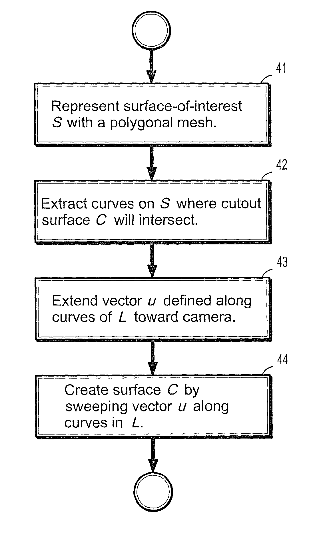
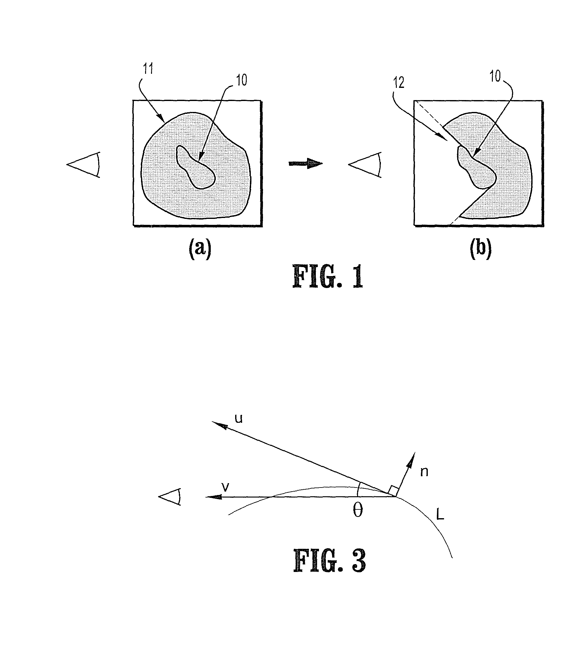
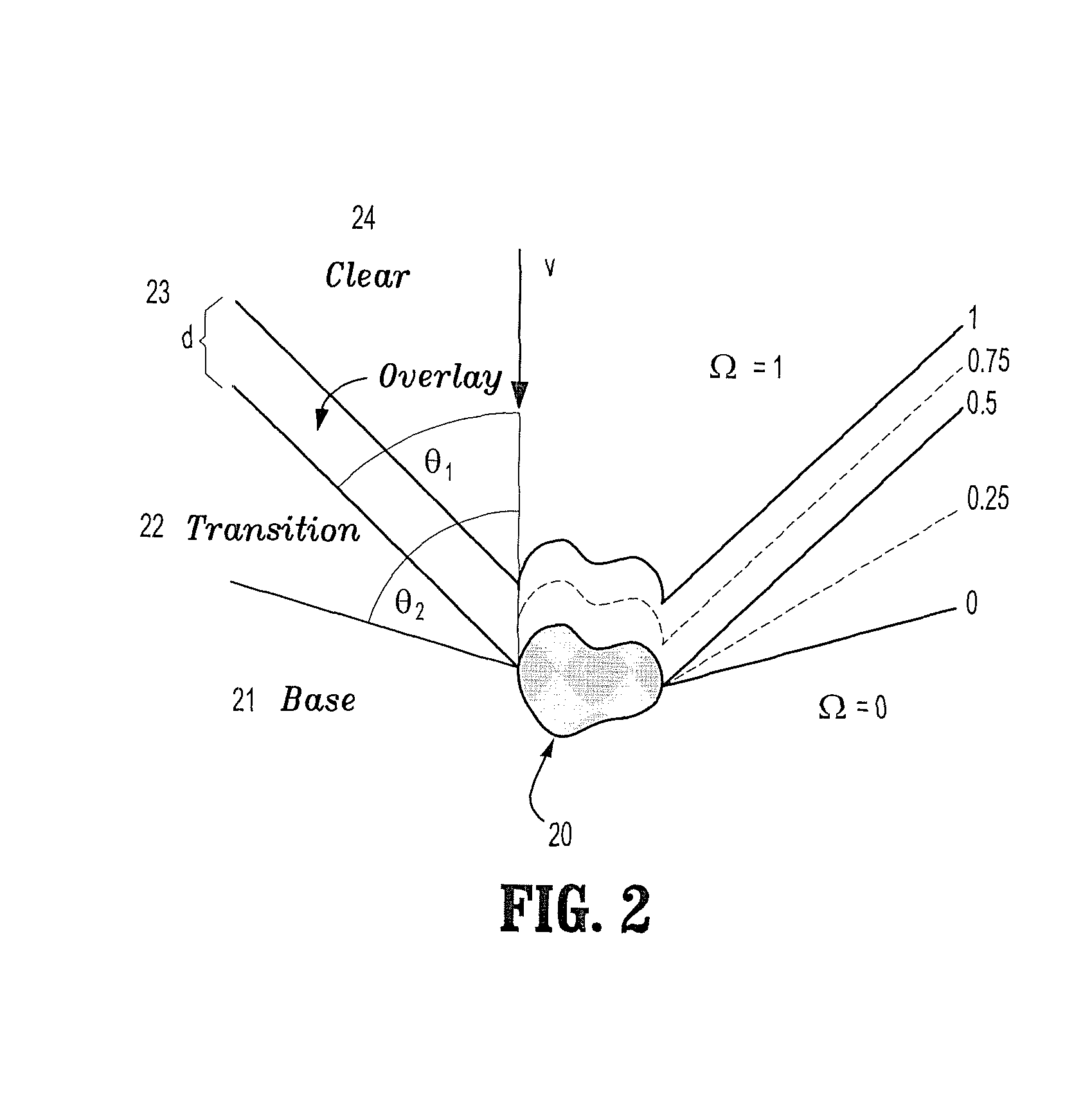
The invention describes a method for creating cutaway views of medical images using an extruded depth buffer. The method involves creating a geometric representation of the carved region and using traditional slice-based hardware volume rendering in conjunction with hardware depth testing to create the final cutout effect. The method allows for creating images that expose the region of interest from all viewpoints. The cutout surface is created by identifying a surface of interest, representing it by a polygonal mesh, extracting curves on the surface where the cutout surface will intersect, extending a vector defined on one of the curves towards a viewing point, and sweeping the extended vector along the curve to create the cutout surface. The angle between the surface tangent and a vector from the surface to a viewing point satisfies a relation. The invention also provides a program storage device that includes instructions for performing the method steps for creating a cutout surface for volume rendering.

Problems solved by technology

When rendering the volume in which they lie, placing emphasis on segmented regions can be challenging using traditional rendering methods, as regions embedded in tissue and bone can be obscured by this material.
The issue that interesting structures are partly or completely occluded by surrounding tissue is frequently encountered in volume visualization.
This is challenging to resolve by traditional view independent approaches, such as transfer function specification.
However, by removing occluding features using the transfer function, the context surrounding an important feature is lost.
Consequently, importance-driven visualization cannot be applied in this case.

Method used


Image

  • System and method for view-dependent cutout geometry for importance-driven volume rendering
  • System and method for view-dependent cutout geometry for importance-driven volume rendering
  • System and method for view-dependent cutout geometry for importance-driven volume rendering

Examples


Embodiment Construction

[0028]Exemplary embodiments of the invention as described herein generally include systems and methods for creating a cutout geometry for importance-driven volume rendering. Accordingly, while the invention is susceptible to various modifications and alternative forms, specific embodiments thereof are shown by way of example in the drawings and will herein be described in detail. It should be understood, however, that there is no intent to limit the invention to the particular forms disclosed, but on the contrary, the invention is to cover all modifications, equivalents, and alternatives falling within the spirit and scope of the invention.

[0029]As used herein, the term “image” refers to multi-dimensional data composed of discrete image elements (e.g., pixels for 2-D images and voxels for 3-D images). The image may be, for example, a medical image of a subject collected by computer tomography, magnetic resonance imaging, ultrasound, or any other medical imaging system known to one o...


PUM


Abstract

A method for creating a cutout surface for volume rendering includes providing a digitized medical image volume comprising a plurality of intensities corresponding to a 3-dimensional grid of points, identifying a surface of interest in said image volume, representing said surface-of-interest by a polygonal mesh, extracting a set of curves on said surface-of-interest where a cutout surface will intersect, extending a vector defined on one of said curves toward a viewing point, and sweeping said extended vector along said curve to create said cutout surface.

Description

CROSS REFERENCE TO RELATED UNITED STATES APPLICATIONS[0001]This application claims priority from “Creating View-Dependent Cutout Geometry for Importance-Driven Volume Rendering”, U.S. Provisional Application No. 60 / 847,044 of Burns, et al., filed Sep. 25, 2006, the contents of which are herein incorporated by reference.TECHNICAL FIELD[0002]This disclosure is directed to the visualization and volume rendering of digitized medical images.DISCUSSION OF THE RELATED ART[0003]One goal of medical imaging visualization is the visual accentuation of a segmented region of interest in a computed tomography (CT) or magnetic resonance image (MRI) volume. For example, one may wish to view segmented coronary arteries as they are embedded in the heart or to view segmented organs in relation to the torso. These segmentations can come as a result of manual or automatic processes, and are usually represented by a binary mask volume or a polygonal surface. When rendering the volume in which they lie, p...

Claims


Application Information

Patent Timeline
Patent Type & Authority Patents(United States)
IPC IPC(8): G09G5/00
CPCG06T15/08G06T17/20G06T17/10
Inventor BURNS, MICHAELENGEL, KLAUS
Owner SIEMENS MEDICAL SOLUTIONS USA INC
Learn More