
Laser based metal deposition (LBMD) of antimicrobials to implant surfaces

a technology of biocompatible materials and metal deposition, which is applied in the direction of dental implants, solid-state diffusion coatings, elbow joints, etc., can solve the problems of wear or bone ingrowth characteristics, device fatigue properties that cannot be optimized for specific properties of certain portions of implants, and device bearing properties that cannot be improved, so as to improve the bearing properties of implants, increase the bone ingrowth properties of implant surfaces, and improve wear properties

Inactive Publication Date: 2011-05-31
MEDICINELODGE
View PDF114 Cites 14 Cited by
  • Summary
  • Abstract
  • Description
  • Claims
  • Application Information

AI Technical Summary

Benefits of technology

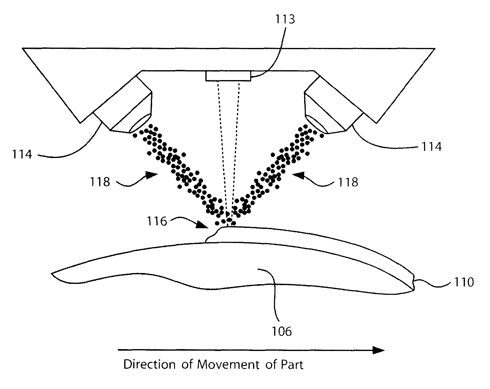
[0018]According to the LBMD material application of the present invention, the applied material can be applied as, for example, powdered metal, as a wire or as a foil. The applied material is then melted by a high-energy laser immediately upon or soon after application. The use of a laser to heat the applied material advantageously allows the heating to be very localized, thereby minimizing any adverse effects of such heat on the underlying material. However, in this invention, other sources of energy such as plasma and electron beam energy could also be focused and localized to allow energy based metal deposition of material through similar processes. Thus, in this invention laser energy is the preferred energy source. However it is understood that the term Laser Based Metal Deposition (LBMD) is meant to include any other energy source that can provide sufficient energy locally to melt and deposit the additive material, but minimize any adverse effects of such heat on the underlying base material.
[0036]The systems and methods of the present invention may be used to provide a number of different types of implant surfaces, including bone apposition surfaces, articular surfaces, and surfaces that do not abut bone or articulate. Bone apposition surfaces may be deposited with a relatively high porosity to enhance bone in-growth. Articular surfaces may be formed with a higher hardness to provide enhanced wear resistance. A wide variety of implant surfaces, including those that do not articulate or contact bone, may desirably be formed with antimicrobial properties to reduce the probability of infection of the tissues surrounding the implantation site.

Problems solved by technology

The development of such devices has confronted scientists and engineers with many technical challenges, such as in the area of materials science engineering wherein to achieve optimal implant performance various biocompatible materials with different physical and mechanical properties are bonded to each other.
Since a device such as an artificial joint must undergo a great number of cycles of wear during the lifetime of the host patient, such devices must also possess great fatigue properties.
While this produces an implant device with bulk properties that are optimized for certain overall design criteria such as biocompatibility strength and modulus of elasticity, these properties may not be optimized for property requirements specific to certain portions of the implant, such as wear or bone ingrowth characteristics.
For instance, while the use of porous materials such as porous Ti provides crucial and beneficial bonding properties, such materials may not have optimal properties in other areas.
For example, porous materials may not be as hard as some other biocompatible materials and therefore may not have acceptable wear properties.
However, because of the overriding importance of strong permanent bonding with the host patient bone, such porous materials have continued to be used in spite of less than optimal wear properties.
One challenge to using such a technique is that of achieving a sufficiently strong, permanent bond between the first and second portions, without the use of adhesives that may be biologically incompatible or may fail under the stresses imposed by the body of the patient.
Attempting to weld such materials together can cause the non-porous material to flow into the porous material, destroying the porosity of the porous material and degrading the ability of the device to bond with the patient's bone.
In addition, such materials, being dissimilar metals, often experience galvanic corrosion when bonded together in such a manner.

Method used


Image

  • Laser based metal deposition (LBMD) of antimicrobials to implant surfaces
  • Laser based metal deposition (LBMD) of antimicrobials to implant surfaces
  • Laser based metal deposition (LBMD) of antimicrobials to implant surfaces

Examples


Embodiment Construction

[0062]The following description is the best embodiment presently contemplated for carrying out this invention. This description is made for the purpose of illustrating the general principles of this invention and is not meant to limit the inventive concepts claimed herein.

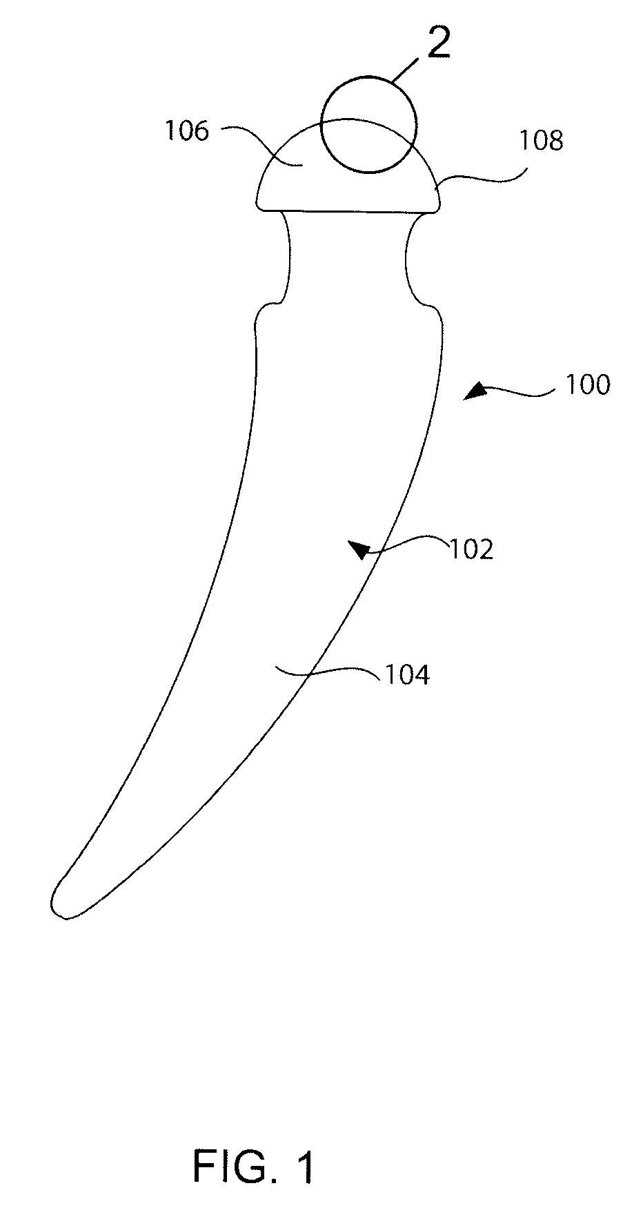
[0063]With reference to FIG. 1, a preferred embodiment of the present invention will be described in terms of a hip prosthesis (hip) 100 for implanting in the body of a patient. However, this is only by way of example, and it should be understood the present invention can practiced on many other medically implanted devices, including without limitation, knee, shoulder and elbow prostheses, as well as many other devices. Note FIG. 5, discussed below.

[0064]The hip prostheses 100 must be constructed completely of biocompatible materials in order to ensure acceptance of the prostheses by the patient's body. A biocompatible material is one that will not cause an adverse reaction with a host patient, and that will not co...


PUM

PropertyMeasurementUnit
thicknessaaaaaaaaaa
thickaaaaaaaaaa
thickaaaaaaaaaa

Abstract

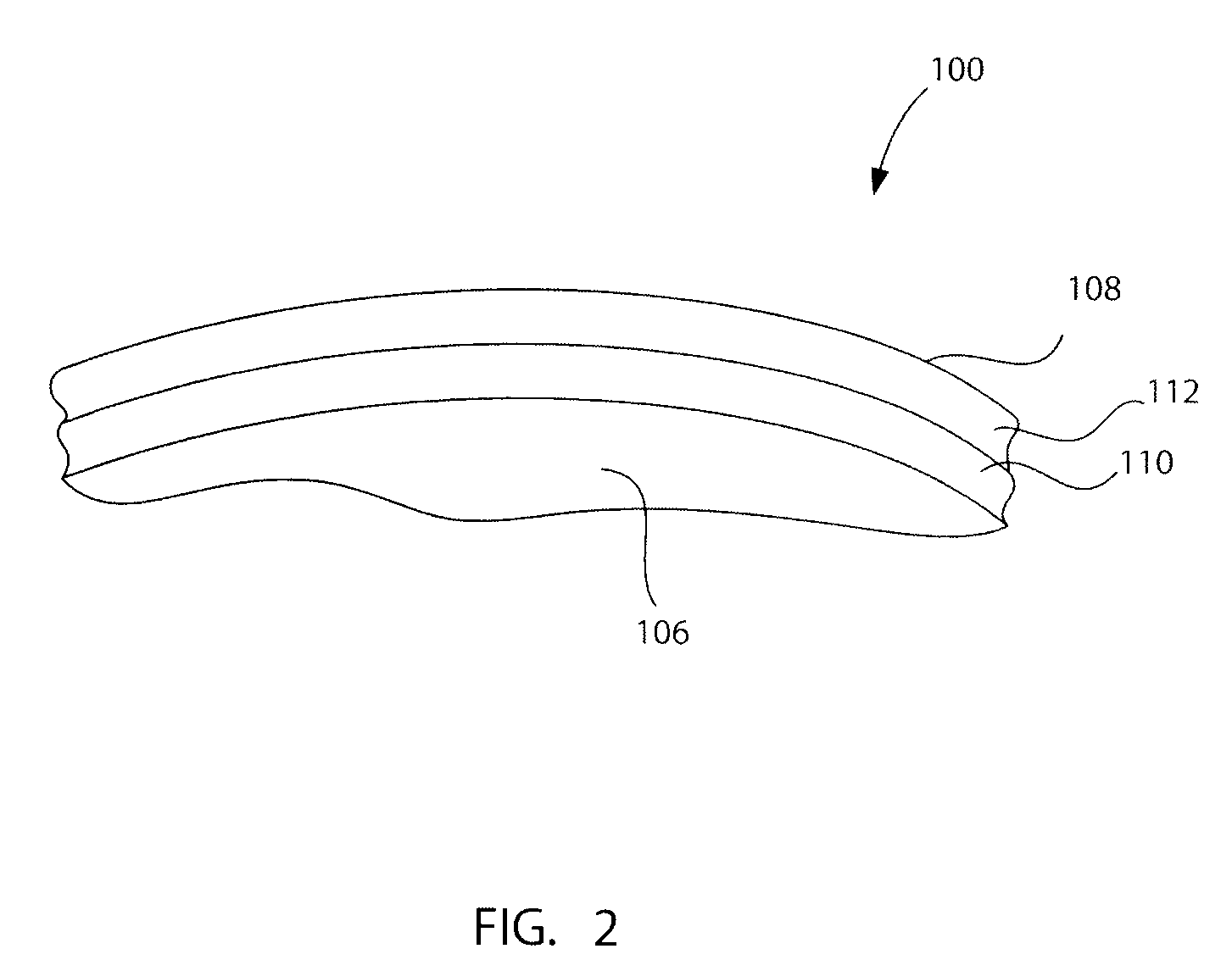
A method is provided for depositing a hard wear resistant surface onto a porous or non-porous base material of a medical implant. The wear resistant surface of the medical implant device may be formed by a Laser Based Metal Deposition (LBMD) method such as Laser Engineered Net Shaping (LENS). The wear resistant surface may include a blend of multiple different biocompatible materials. Further, functionally graded layers of biocompatible materials may be used to form the wear resistant surface. Usage of a porous material for the base may promote bone ingrowth to allow the implant to fuse strongly with the bone of a host patient. The hard wear resistant surface provides device longevity, particularly when applied to bearing surfaces such as artificial joint bearing surfaces or a dental implant bearing surfaces. An antimicrobial material such as silver may be deposited in combination with a metal to form an antimicrobial surface deposit.

Description

CROSS-REFERENCE TO RELATED DOCUMENTS[0001]This application claims the benefit of:[0002]Pending prior U.S. Provisional Patent Application No. 60 / 811,934, filed Jun. 7, 2006 by Brent E. Stucker, et al. for INCORPORATION OF SILVER INTO MATERIALS DEPOSITED BY LBMD, which is incorporated herein by reference.[0003]The following are also incorporated herein by reference:[0004]Pending prior U.S. patent application Ser. No. 11 / 432,426, filed May 10, 2006 by Daniel F. Justin et al. for LASER BASED METAL DEPOSITION (LBMD) OF IMPLANT STRUCTURES;[0005]Pending prior U.S. patent application Ser. No. 11 / 253,850 filed Oct. 18, 2005 by Daniel F. Justin et al. for LASER BASED METRAL DEPOSITION OF IMPLANT STRUCTURES;[0006]Issued U.S. patent application Ser. No. 10 / 811,038, filed Mar. 26, 2004 by Daniel F. Justin et al. for LASER ENGINEERED NET SHAPING OF IMPLANT STRUCTURES, issued as U.S. Pat. No. 7,001,672 on Feb. 21, 2006; and[0007]Prior U.S. Provisional Patent Application No. 60 / 527,118, filed Dec. ...

Claims


Application Information

Patent Timeline
Patent Type & Authority Patents(United States)
IPC IPC(8): B05D3/00C21D1/09B32B15/00
CPCA61F2/30767A61F2/36A61F2/3859A61F2/4225A61F2/4241A61L27/04A61L27/30A61L27/54B23K26/34C23C4/12C23C24/10C23C26/00C23C26/02B23K26/3206A61C8/0012A61F2/3099A61F2/3662A61F2/38A61F2/3804A61F2/40A61F2/4261A61F2002/30451A61F2002/30604A61F2002/30733A61F2002/30805A61F2002/30878A61F2002/30922A61F2002/30925A61F2002/30929A61F2002/30934A61F2002/30967A61F2002/3097A61F2002/30971A61F2002/3611A61F2002/3625A61F2002/3652A61F2002/4253A61F2220/0058A61F2310/00017A61F2310/00023A61F2310/00029A61F2310/00089A61F2310/00095A61F2310/00131A61F2310/00149A61F2310/00293A61F2310/00395A61F2310/00401A61F2310/00407A61F2310/00413A61F2310/00467A61F2310/00473A61F2310/00485A61F2310/00491A61F2310/00514A61F2310/0052A61F2310/00532A61F2310/00544A61F2310/00556A61F2310/00562A61F2310/00568A61L2300/102A61L2300/104A61L2300/404Y10T428/12847Y10T428/12771Y10T428/12458Y10T428/12493Y10T428/12479B23K26/147B23K26/32B23K26/144B23K2103/50
Inventor JUSTIN, DANIEL F.STUCKER, BRENT E.GABBITA, DURGA JANAKI RAMBRITT, DAVID WILLIAM
Owner MEDICINELODGE
Learn More