Rail system and X-ray imaging apparatus using the same
a technology of x-ray imaging and rail system, which is applied in the direction of instruments, tubes with screens, image-conversion/image-amplification tubes, etc., can solve the problems of increasing installation costs, spatial limitations, and height of ceilings that must be able to vary, so as to reduce installation space and increase the space available for movement
- Summary
- Abstract
- Description
- Claims
- Application Information
AI Technical Summary
Benefits of technology
Problems solved by technology
Method used
Image
Examples
first embodiment
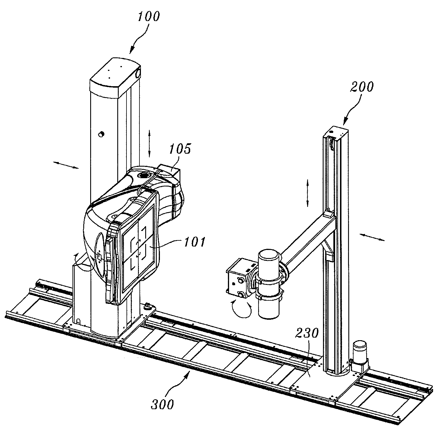
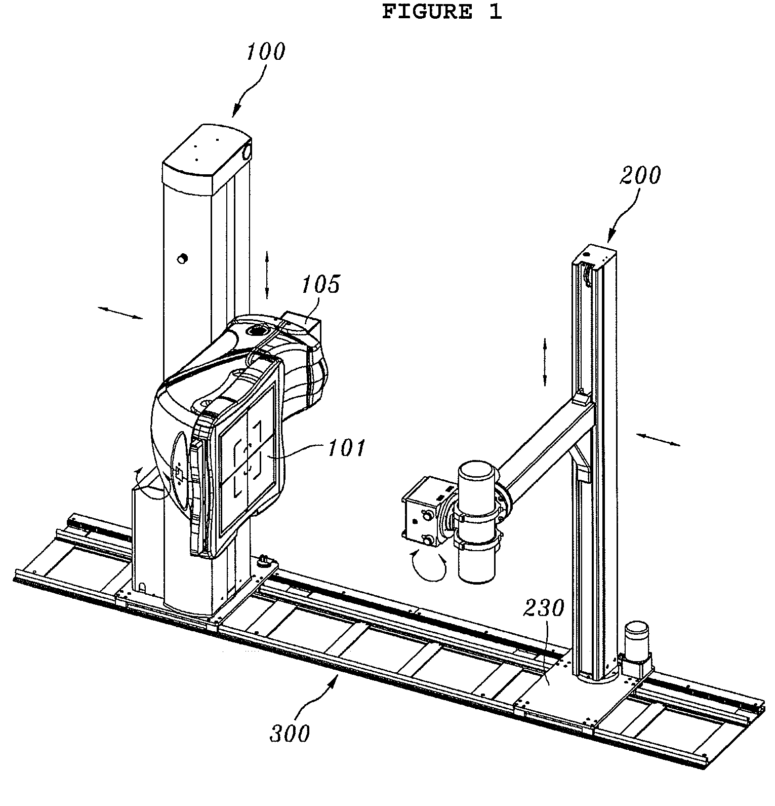
[0031]FIG. 1 is a perspective view illustrating a rail system, provided with a detector arm having a bent structure, and an X-ray imaging apparatus using the rail system, according to the present invention.
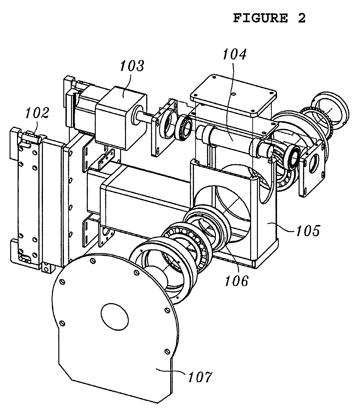
[0032]FIG. 2 is an exploded perspective view showing the detector arm of the rail system according to the first embodiment of the present invention.
[0033]FIG. 3 is a perspective view illustrating a detector stand of the rail system according to the first embodiment of the present invention.
[0034]FIG. 4 is an exploded perspective view illustrating a tube stand of the rail system according to the first embodiment of the present invention.
[0035]FIG. 5 is a perspective view illustrating a method of moving the X-ray imaging apparatus along the rail system according to the first embodiment of the present invention.
[0036]FIG. 6 is a perspective view showing the operation of the X-ray imaging apparatus according to the first embodiment of the present invention when imaging a patient who i...
second embodiment
[0105]FIG. 9 is a perspective view illustrating a rail system, provided with a tube arm having a bent structure, and an X-ray imaging apparatus using the rail system, according to the present invention.
[0106]In the following description of the rail system and the X-ray imaging apparatus according to the second embodiment of the present invention, the description pertaining to the same elements as those of the rail system and the X-ray imaging apparatus according to the first embodiment will be skipped, and only elements different therefrom will be explained.
[0107]In the second embodiment, a detector arm 105 is provided on a front surface of a detector stand 115 so as to be movable upwards and downwards.
[0108]The tube arm 206 having the bent structure is coupled to the tube stand 210 so as to be movable upwards and downwards such that the distal end of the tube arm 206 faces a detecting unit 100.
[0109]The operation of the rail system, provided with the tube arm 206 having the bent st...
third embodiment
[0121]FIG. 10 is a perspective view illustrating a rail system, provided with two rails and a detector arm having a bent structure, and an X-ray imaging apparatus using the rail system, according to the present invention.
[0122]As shown in FIG. 10, a detecting unit 100 provided the detector arm 105 having the bent structure may be provided on a first rail 306a, and an X-ray generating unit 200 may be provided on a second rail 306b.
[0123]Alternatively, a detecting unit 100 may be provided on the first rail 306a, and an X-ray generating unit 200 provided with a tube arm 206 having a bent structure may be provided on the second rail 306b.
[0124]The operation of the rail system having the two rails and the X-ray imaging apparatus using this rail system according to the third embodiment of the present invention is the same as that of the rail system having the single rail and the X-ray imaging apparatus using this rail system according to the first or second embodiment of the present inv...
PUM
| Property | Measurement | Unit |
|---|---|---|
| height | aaaaa | aaaaa |
| distance | aaaaa | aaaaa |
| height | aaaaa | aaaaa |
Abstract
Description
Claims
Application Information
 - R&D
- Intellectual Property
- Life Sciences
- Materials
- Tech Scout
- Unparalleled Data Quality
- Higher Quality Content
- 60% Fewer Hallucinations
Browse by: Latest US Patents, China's latest patents, Technical Efficacy Thesaurus, Application Domain, Technology Topic, Popular Technical Reports.
© 2025 PatSnap. All rights reserved.Legal|Privacy policy|Modern Slavery Act Transparency Statement|Sitemap|About US| Contact US: help@patsnap.com


