
Feather board apparatus and method

a technology of feather board and finger, which is applied in the direction of metal sawing devices, flat surface machines, manufacturing tools, etc., can solve the problems of feather board distal end so large, piece along the guide surface, and friction,

Active Publication Date: 2011-05-17
NOMIS LLC
View PDF8 Cites 14 Cited by
  • Summary
  • Abstract
  • Description
  • Claims
  • Application Information

AI Technical Summary

Benefits of technology

"The invention is a feather board apparatus and method for holding a work piece in place as it is guided along a guide surface. The feather board has a clamping arrangement that allows for limited motion in the direction opposite to the direction of feed. This results in a reduced amount of slippage as the work piece is fed through the guide surface. The feather board also has a contact plane that is spaced from the guide surface, allowing for a limited amount of pushing force as the work piece moves. The clamping arrangements provide a higher contact pressure at the infeed clamping point, which helps to deform the feather board material and restrain its movement. The feather board can be stacked on top of each other for use with taller work pieces. A spacer can be used to separate the feather boards."

Problems solved by technology

For example, a common problem encountered while using feather boards is that, if the feather board is not very precisely positioned, with respect to the guide surface, the pushing force required to feed the work piece along the guide surface, against the friction generated by contact of the work piece with the distal ends of the fingers on the feather board becomes so great, part way through the operation of feeding the work piece past the cutting tool, that the work piece cannot be moved further.
Where feather boards, or other types of attachments or adjustments on tools must be made, prior experience has shown that adjustment or locking knobs, of conventional construction, are often difficult to loosen once they have been tightened.

Method used


Image

  • Feather board apparatus and method
  • Feather board apparatus and method
  • Feather board apparatus and method

Examples


Embodiment Construction

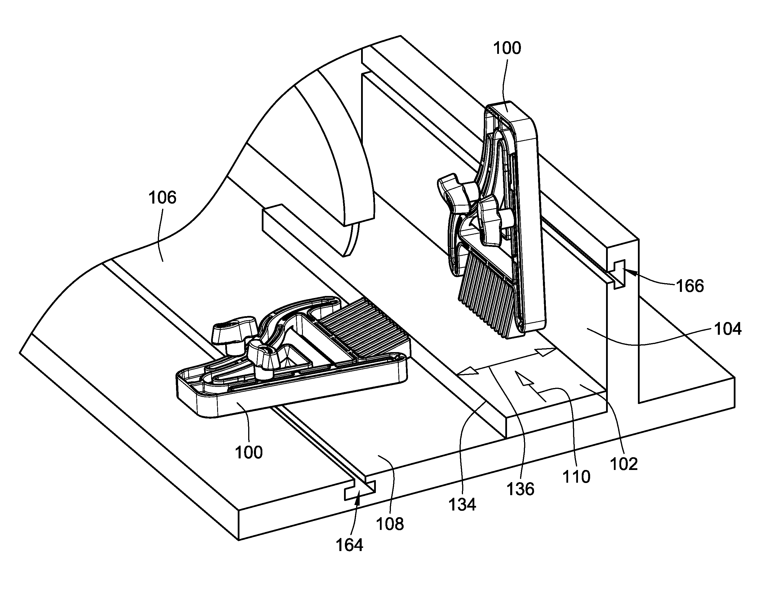
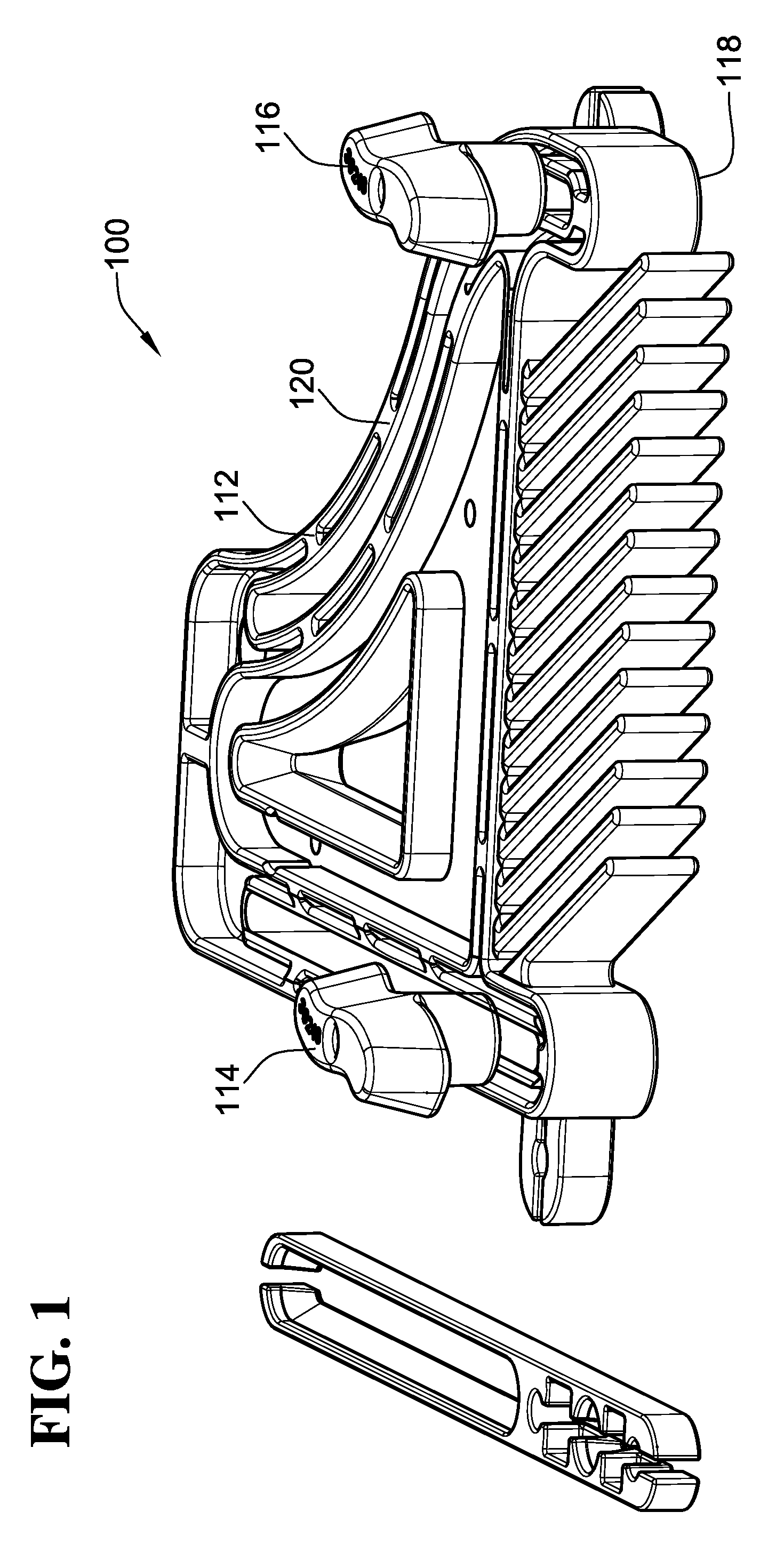
[0031]FIG. 1 shows a first exemplary embodiment of a feather board apparatus 100, according to the invention, for holding a work piece 102 against a guide surface 104 of a machine 106, in the manner shown in FIG. 11, as the work piece 102 is guided across a table 108 of the machine 106 in a feed direction indicated by arrow 110. As shown in FIG. 1, the first exemplary embodiment of the feather board apparatus includes a feather board body 112, an infeed side feather board clamping arrangement 114 and an outfeed side feather board clamping arrangement 116.

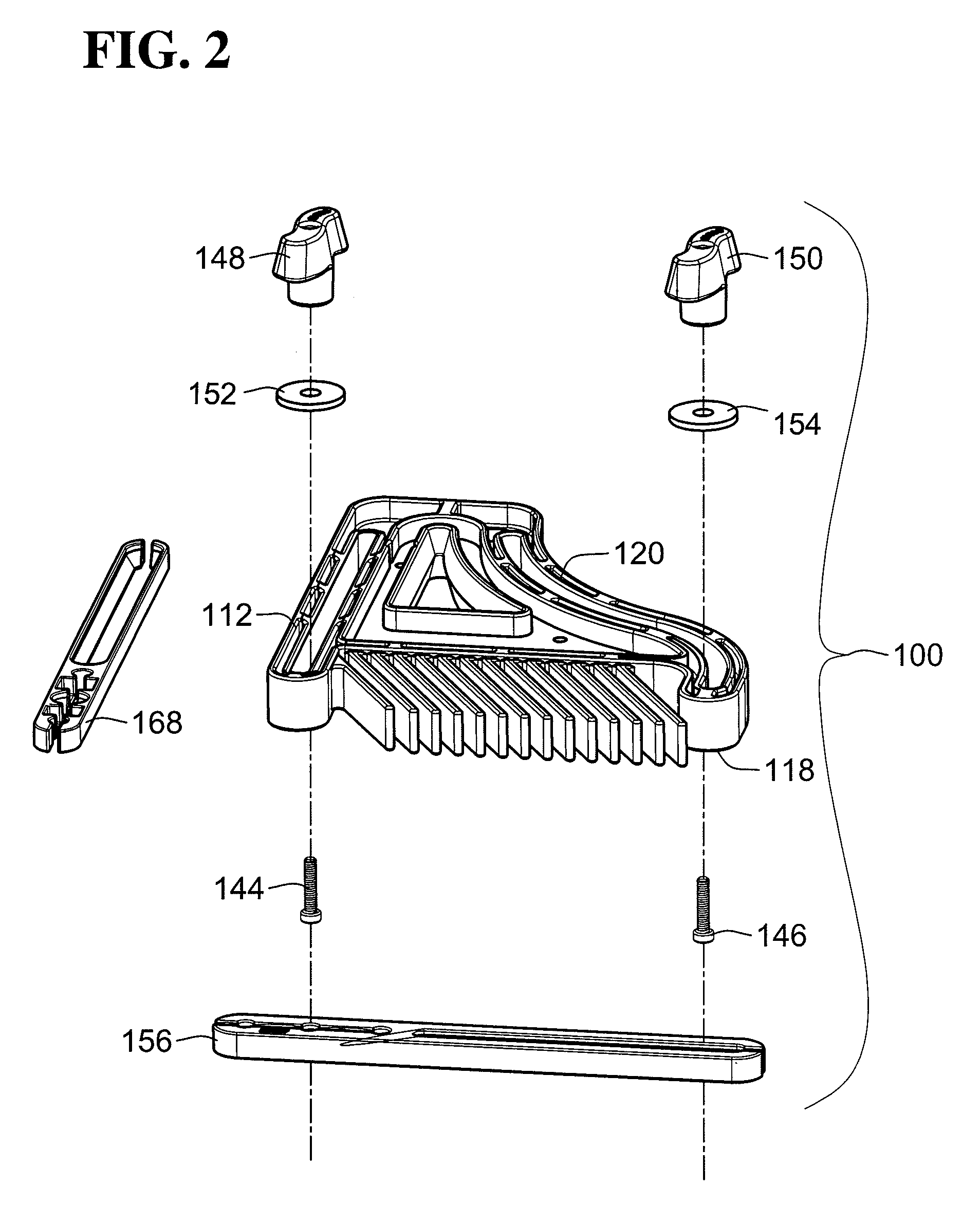
[0032]As shown in FIGS. 2 and 3, the feather board body 112 defines first and second faces 118, 120 thereof (corresponding to a lower and an upper surface as shown in FIGS. 1-3). As best seen in FIG. 3, the feather board body 112 also defines a longitudinal axis 122 of the feather board body 112 infeed and outfeed sides 124, 126 disposed on opposite sides of the longitudinal axis 122, and a transverse edge 128 connecting the first a...


PUM

PropertyMeasurementUnit
pressureaaaaaaaaaa
clamping pressureaaaaaaaaaa
torqueaaaaaaaaaa

Abstract

An improved feather board apparatus and method are provided, for use in holding a work piece against a guide surface as the work piece is guided in a feed direction, and for precluding motion of the work piece in a direction opposite the feed direction, through use of a feather board apparatus, having a feather board clamping arrangement which allows for limited amount of pivoting of the feather board about an in feed side clamping point, as the work piece is fed past the feather board.

Description

CROSS-REFERENCE TO RELATED PATENT APPLICATIONS[0001]This patent application claims the benefit of U.S. Provisional Patent Application No. 60 / 916,533, filed May 7, 2007, the disclosure and teachings of which are incorporated herein, in their entireties, by reference.FIELD OF THE INVENTION[0002]This invention relates to machines and tools for cutting materials, such as wood, and more particularly to fixtures such as feather boards for clamping a work piece against a guide surface, as the work piece is moved past a cutting tool, for maintaining a desired position of the work piece and / or precluding kick-back of the work piece.BACKGROUND OF THE INVENTION[0003]Feather boards have been used for decades to hold a work piece against a guide surface, as the work piece was guided in a feed direction to a cutting tool. Such feather boards traditionally have a series of fingers extending from one edge thereof, positioned adjacent to the guide surface but spaced a clearance distance therefrom, s...

Claims


Application Information

Patent Timeline
Patent Type & Authority Patents(United States)
IPC IPC(8): B27C1/12B27B31/00
CPCB23D47/04B27C5/06B27B25/10Y10T83/6572Y10T83/04Y10T83/745Y10T83/741
Inventor KOZINA, DAMIAN A.ADKINS, EDWARD D.
Owner NOMIS LLC
Learn More