Maximum intensity projection performing method and apparatus

a technology of maximum intensity and projection, applied in the field of maximum intensity projection, can solve the problems of inconvenient capture of a number of mip images in different projection directions, difficult to grasp the deepest extending state of the blood vessel, etc., and achieve the effect of relatively gentle attenuation of one of the two weighting functions

Inactive Publication Date: 2011-04-26
GE MEDICAL SYST GLOBAL TECH CO LLC
View PDF12 Cites 1 Cited by
  • Summary
  • Abstract
  • Description
  • Claims
  • Application Information

AI Technical Summary

Benefits of technology

[0015]To obtain a global maximum and a local maximum, preferably, attenuation of one of the two weighting functions is relatively gentle, and that of the other weighting function is relatively sharp.

Problems solved by technology

Therefore, the relations of blood vessels in depth are not clearly seen and it is difficult to grasp the blood vessel extending state in depth.
However, it is inconvenient to capture a number of MIP images in different projection directions.

Method used


Image

  • Maximum intensity projection performing method and apparatus
  • Maximum intensity projection performing method and apparatus
  • Maximum intensity projection performing method and apparatus

Examples


Embodiment Construction

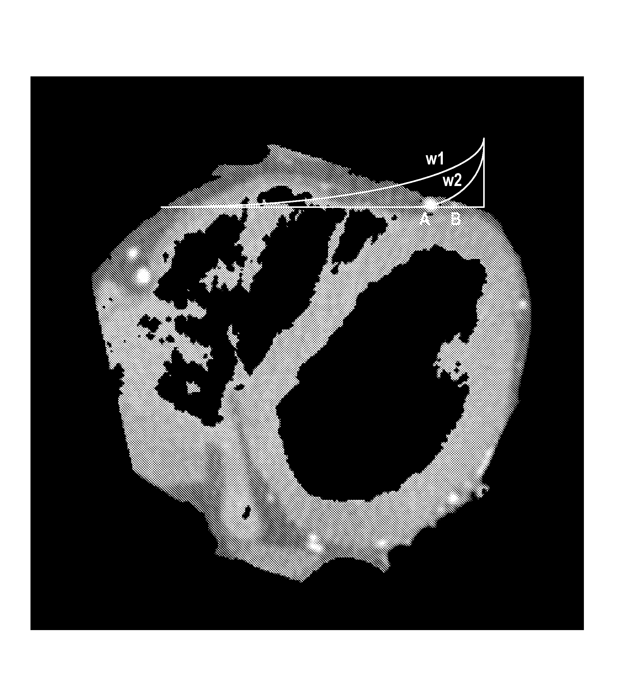
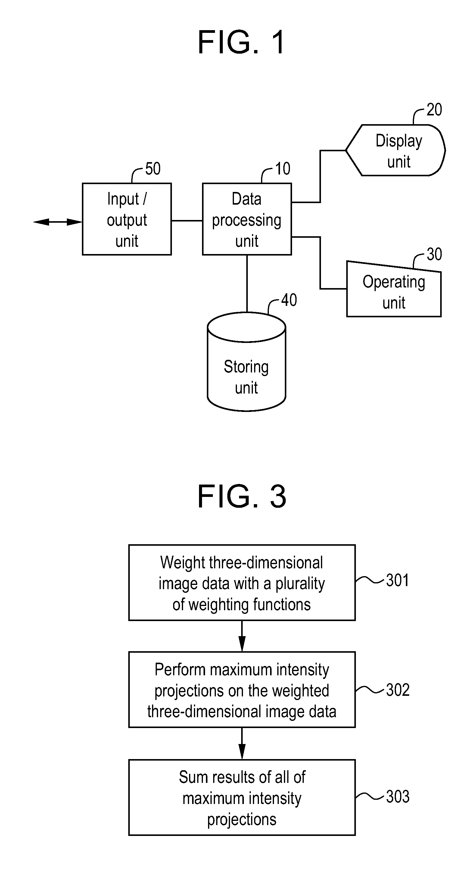
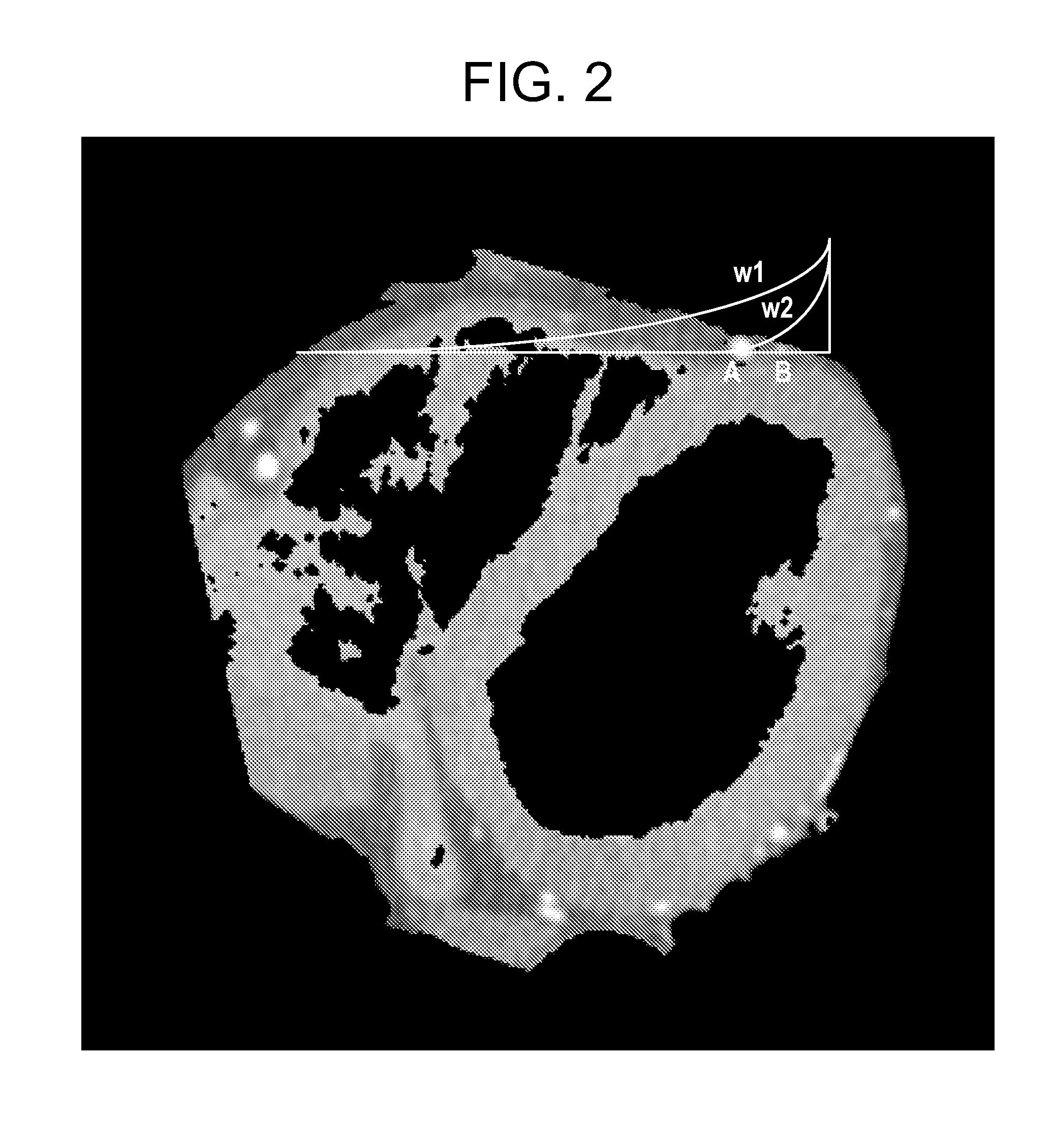
[0024]A best mode for carrying out the present invention will be described hereinbelow with reference to the drawings. The present invention is not limited to the best mode for carrying out the invention. FIG. 1 is a block diagram showing the configuration of an image processing apparatus.

[0025]The apparatus is an example of the best mode for carrying out the invention. By the configuration of the apparatus, an example of the best mode for carrying out the invention related to a maximum intensity projection performing apparatus is shown. By the operation of the apparatus, an example of the best mode for carrying out the invention related to a maximum intensity projection performing method is shown.

[0026]As shown in FIG. 1, the apparatus has a data processing unit 10, a display unit 20, an operating unit 30, a storing unit 40, and an input / output unit 50.

[0027]The data processing unit 10 performs a predetermined data process on data stored in the storing unit 40 on the basis of an in...


PUM


Abstract

In order to visualize a narrow blood vessel overlapping a thick blood vessel, at the time of performing a maximum intensity projection on three-dimensional image data, three-dimensional image data is weighted with a plurality of weighting functions of different attenuation characteristics along a projection line. Maximum intensity projections are performed on the plurality of pieces of the weighted three-dimensional image data, and results of all of the maximum intensity projections are summed. The weight of the weighting function is zero until the projection line reaches the surface of an image and, after the reach, gradually decreases from an initial value. Alternatively, the weight of the weighting function is zero to some midpoint of the projection line and, after the midpoint, gradually decreases from the initial value. The midpoint is adjustable. The attenuation characteristic is given by an exponential function. Parameters of the exponential function are adjustable.

Description

CROSS REFERENCE TO RELATED APPLICATIONS[0001]This application claims the benefit of Japanese Application No. 2006-104970 filed Apr. 6, 2006.BACKGROUND OF THE INVENTION[0002]The present invention relates to a maximum intensity projection (MIP) performing method and apparatus and, more particularly, to a method and apparatus for performing a maximum intensity projection on three-dimensional image data.[0003]In the case of imaging an extending state of blood vessels in a body, a maximum intensity projection on three-dimensional image data captured by angiography or the like is performed. The maximum intensity projection is performed by extracting the maximum image data encountered by a projection line passing a data space on a projection line unit basis. The maximum intensity projection is also called MIP. The image obtained by the maximum intensity projection is also called an MIP image (refer to, for example, Japanese Patent Laid-Open No. Hei 11(1999)-056840).[0004]An MIP image does ...

Claims


Application Information

Patent Timeline
Patent Type & Authority Patents(United States)
IPC IPC(8): G06K9/00A61B5/055A61B6/03G01R33/32G06T1/00
CPCA61B6/463G06T15/08A61B6/504A61B6/481
Inventor HAQUE, HASNINE A.KESERCI, BILGIN
Owner GE MEDICAL SYST GLOBAL TECH CO LLC
Why Eureka
Try Eureka