
Electrospray device

a technology of electrospray and liquid accumulator, which is applied in the direction of particle separator tube details, dispersed particle separation, separation process, etc., can solve the problems of accumulating liquid accumulation adversely affecting the performance of electrospray operation, and no solution to liquid accumulation had been sought. , to prevent back spray and shortening, prevent the accumulation of excess electrospray fluid, and prolong the effect of operation

Active Publication Date: 2011-04-26
BUSEK
View PDF1 Cites 22 Cited by
  • Summary
  • Abstract
  • Description
  • Claims
  • Application Information

AI Technical Summary

Benefits of technology

"The invention is an improved electrospray device that prevents buildup of excess electrospray fluid, reduces back spray and shorting due to electrospray fluid accumulation, enables extended operation and use in environments where cleaning or replacement is not practical, reduces time and cost for cleaning or replacement necessitated by electrospray accumulation, provides improved operation by eliminating the effect of free surfaces in electric fields affecting electrospray, enables smaller and more compact devices through denser arrays of electrospray emitters, and reduces excess electrospray accumulation by making the extractor plate and one or more accelerator plates and shaping plates from a porous, conductive medium for transporting excess, accumulated electrospray fluid away from the aperature."

Problems solved by technology

During electrospray operation, and particularly during startup or with certain applied voltages and / or liquid flowrates applied to the electrospray, the electrospray may deposit some amount of sprayed liquid upon the solid edges of the grids (overspray), especially proximate the aperture.
Accumulated build-up of this deposited liquid adversely impacts performance of electrospray operation over time, particularly when low vapor pressure liquids are used.
Because this accumulation is gradual and most applications are short-duration, performance impacts had been negligible and no solutions to liquid accumulation had been sought.
For extended electrospray operation e.g. for durations exceeding 100 hours, or for particular operating conditions, no effective means for transport / removal of accumulated liquid exists.
Consequently, duration of electrospray operation is limited to the point where the accumulated liquid interferes with, and ultimately prevents, proper function.
Frequent cleaning or replacement of components is costly, and for applications where cleaning or replacement is impossible, the duration of electrospray operation is limited to the time it takes for some critical buildup preventing proper operation.

Method used


Image

  • Electrospray device
  • Electrospray device
  • Electrospray device

Examples


Embodiment Construction

[0028]Aside from the preferred embodiment or embodiments disclosed below, this invention is capable of other embodiments and of being practiced or being carried out in various ways. Thus, it is to be understood that the invention is not limited in its application to the details of construction and the arrangements of components set forth in the following description or illustrated in the drawings. If only one embodiment is described herein, the claims hereof are not to be limited to that embodiment. Moreover, the claims hereof are not to be read restrictively unless there is clear and convincing evidence manifesting a certain exclusion, restriction, or disclaimer.

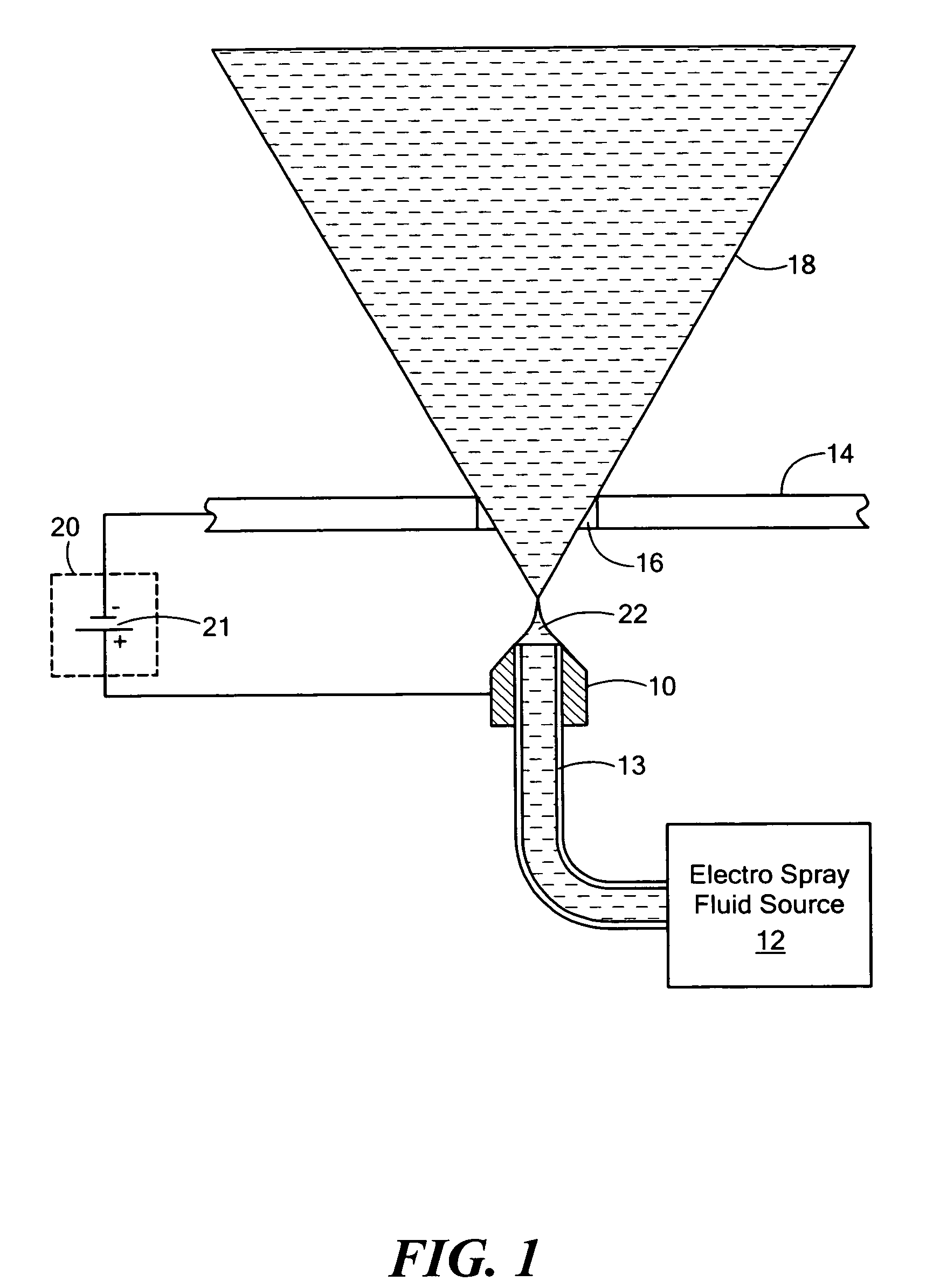
[0029]As explained in the Background, electrospray devices such colloid thrusters employ extraction and acceleration grids to create and accelerate liquid propellant as charged droplets and ions. A small fraction of the emitted propellant, usually much less than 1%, is intercepted by the grids where it may accumulate. The m...


PUM


Abstract

An electrospray device includes an electrospray emitter adapted to receive electrospray fluid; an extractor plate spaced from the electrospray emitter and having at least one aperature; and a power supply for applying a first voltage between the extractor plate and emitter for generating at least one Taylor cone emission through the aperature to create an electrospray plume from the electrospray fluid, the extractor plate as well as accelerator and shaping plates may include a porous, conductive medium for transporting and storing excess, accumulated electrospray fluid away from the aperature.

Description

RELATED APPLICATIONS[0001]This application claims benefit of and priority to U.S. Provisional Application Ser. No. 61 / 137,410 filed Jul. 30, 2008 under 35 U.S.C. §§119, 120, 363, 365, and 37 C.F.R. §1.55 and §1.78 incorporated herein by this reference.[0002]Some work pertaining to this invention has been done under government contract: NASA NAS7-1407 / Subcontract No. 1247199; United States Air Force FA8650-04-C2504; and HQ0006-05-C-7235. The Government may have certain rights under the subject invention.FIELD OF THE INVENTION[0003]This invention relates to an improved electrospray device and more particularly to an electrospray device which avoids excess accumulation of electrospray fluid.BACKGROUND OF THE INVENTION[0004]Basic operation of electrosprays is well-known and characterized in a large number of publications and used in many applications. Most of these applications are distinguished by relatively short-duration operation, especially where the electrospray is emitted through...

Claims


Application Information

Patent Timeline
Patent Type & Authority Patents(United States)
IPC IPC(8): H01J49/10
CPCH01J49/165
Inventor DEMMONS, NATHANIELMARTIN, ROYHRUBY, VLADIMIRROY, THOMASSPENCE, DOUGLASEHRBAR, ERICZWAHLEN, JURG
Owner BUSEK
Learn More