
Device for transporting a child

a child and vehicle technology, applied in the field of child transporting devices, can solve problems such as no brakes on wheels

Inactive Publication Date: 2011-04-12
TEAM TEX
View PDF35 Cites 25 Cited by
  • Summary
  • Abstract
  • Description
  • Claims
  • Application Information

AI Technical Summary

Benefits of technology

"The device for transporting a child in a child seat has several technical effects. Firstly, it has a push bar that can be activated from different sides, allowing for easier maneuverability. Secondly, it has pivot locks on the wheels or wheel sets, which ensures that the brakes are activated in the proper position, even when the push bar is in a different position. Thirdly, it has a mechanism that activates the pivot locks simultaneously with the brakes, ensuring proper braking and stability. Fourthly, it has a slide that can adjust the length of the push bar for different individuals, and a spring arm that reduces jolts and discomfort for the child. Fifthly, it has a brake lever that is independent of the position of the push bar, ensuring consistent braking regardless of external factors such as weight or road conditions. Lastly, it has a mechanism that stops the rotation of the wheel by moving a brake lever and a brake pin, preventing unacceptable deformations when the brake is activated."

Problems solved by technology

The disadvantage of the known device is that the wheels have no brakes.
From WO 9307039 brakes for each wheel are known but these brakes have to be actuated for each wheel separately which is a disadvantage.

Method used


Image

  • Device for transporting a child
  • Device for transporting a child
  • Device for transporting a child

Examples


second embodiment

[0047]FIG. 6b shows a top view of the mechanism used for changing the settings of the wheel pivots 11 by rotating the push bar axis 21. In this embodiment the cables 47 are directly connected with their cable ends 99 to the second cam ring 35′ and the fourth cam ring 40′, thereby avoiding backlash and resistance in the various levers. The load on the cam rings 35′, 40′ is equally divided over the circumference which improves the contact between the first cam ring 32 and the second cam ring 35′ and respectively the third cam ring 38 and the fourth cam ring 40′ and improves their movements in longitudinal direction along the push bar axis 21. For guiding the cables 47 to either both first wheel sets or both second wheel sets both cables 47 are guided around a first capstan 97, after passing the capstan 97 one of the cables is connected to the cam ring 35′ or 40′ and the other is looped around a second capstan 98 and then connected to the cam ring 35′ or 40′. The Bowden cables have cab...

third embodiment

[0048]FIG. 6c shows a top view of the mechanism used for changing the settings of the wheel pivots 11 by rotating the push bar axis 21. In this embodiment, a second cam ring 35″ is directly coupled to the cable end 99 and / or the cable shield stop 102 of both Bowden cables to the second wheel sets 15. A fourth cam ring 40″ is also directly coupled to the cable end 99 and / or the cable shield stop 102 of both Bowden cables to the first wheel sets 13. In this embodiment, the cables 47 follow a straight line from the cable shield stops 102 to the cable end 99 and if required are guided through an opening 100 in either the second cam ring 35″ or the fourth cam ring 40″.

[0049]FIG. 7 shows a rendering of the cam surfaces and the interaction between the first cam ring 32 and the second cam ring 35 (or 35′ and 35″ respectively) and respectively the third cam ring 38 and the fourth cam ring 40 (or 40′ and 40″ respectively) as a result of the rotation of the push bar axis 21 which is illustrate...


PUM


Abstract

A device for transporting a child in a child seat includes a main frame for supporting the child seat, a swivable push bar for pushing the main frame from different sides, and pivotable wheels or wheel sets for supporting the main frame whereby the wheels or wheel sets are provided with pivot locks and brakes. The push bar has a brake handle for activating the brakes and the device includes a mechanism for activating the pivot locks of the wheels or wheel sets under the push bar and for simultaneously coupling only the brakes on these wheels or wheel sets with the brake handle.

Description

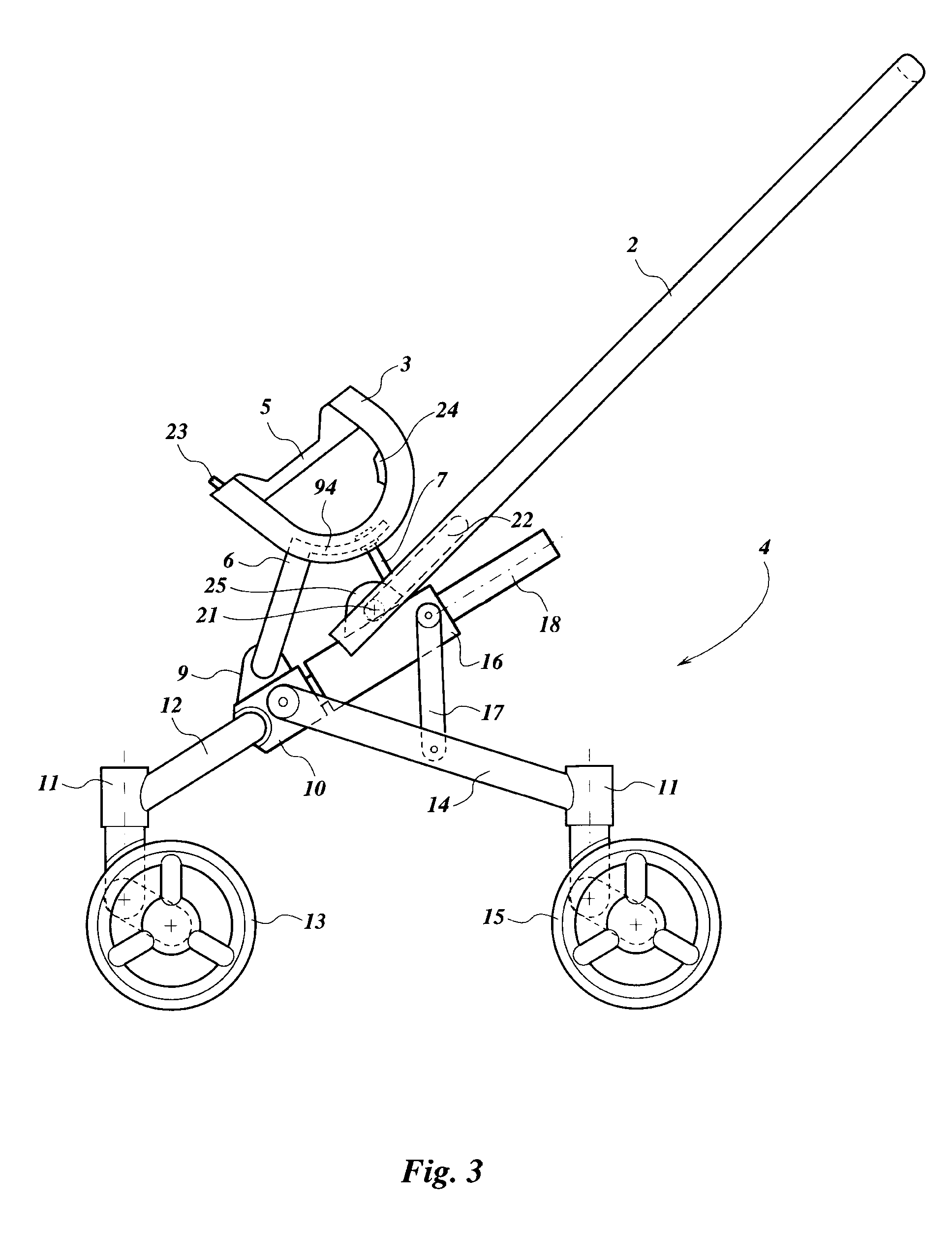
CROSS-REFERENCE TO RELATED APPLICATIONS[0001]The present application claims priority from European patent application no. 07104252, filed Mar. 15, 2007, the content of which is incorporated herein by reference.FIELD OF THE INVENTION[0002]The invention concerns a device for transporting a child in a child seat (1) comprising a main frame (16) for supporting the child seat, a swivable push bar (2) for pushing the main frame from different sides, pivotable wheels or wheel sets (13,15) for supporting the main frame whereby the wheels or wheel sets are provided with pivot locks (69) characterized in that the push bar (2) comprises a brake handle for activating the brakes (88,93) in the wheels or wheel sets (13,15) and that the device comprises a mechanism (32,35,38,40,42,58,61) for activating the pivot locks (69) of the wheels or wheel sets under the push bar and for simultaneously coupling only the brakes on these wheels or wheel sets with the brake handle.BACKGROUND OF THE INVENTION[00...

Claims


Application Information

Patent Timeline
Patent Type & Authority Patents(United States)
IPC IPC(8): B62B7/04
CPCB62B7/068B62B9/20B62B9/14B62B5/065B62B9/203
Inventor VAN DER VEGT, HERMAN
Owner TEAM TEX
Learn More