
Event notification system for an appliance

a technology for event notification and appliances, applied in the field of data acquisition engines and systems for appliances, can solve the problems of difficult design, development, testing, diagnosis, control, and debugging of basic appliance models

Active Publication Date: 2011-03-29
WHIRLPOOL CORP
View PDF83 Cites 39 Cited by
  • Summary
  • Abstract
  • Description
  • Claims
  • Application Information

AI Technical Summary

Benefits of technology

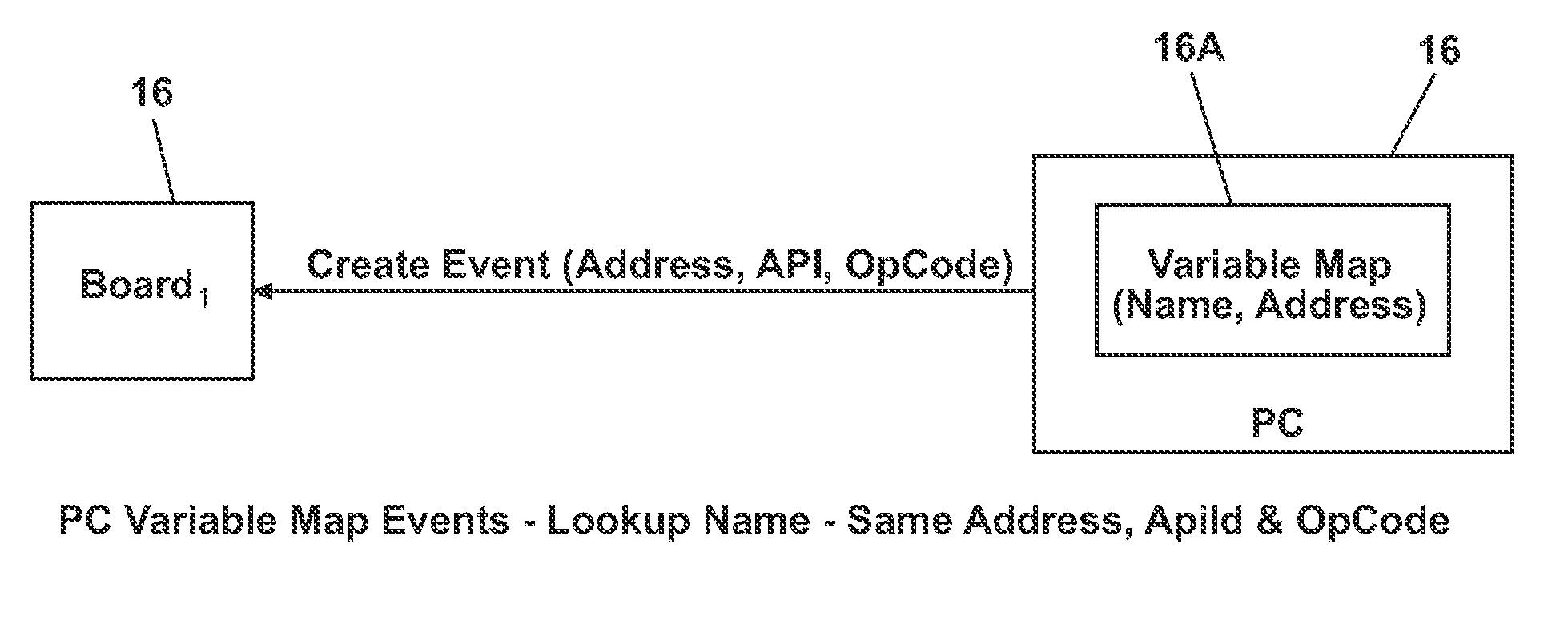
The invention is a system and control system that use a memory heap to dynamically generate event structures with pointers, operators, and arguments. These structures are then evaluated by a data acquisition engine to determine if they meet certain conditions, resulting in a notification message if a true condition is found. This allows for real-time monitoring and control of devices in a useful cycle of operation.

Problems solved by technology

The basic appliance models typically are difficult to design, develop, test, diagnose, control, and debug due to the diversity of componentry and the associated diversity of implementation choices.

Method used


Image

  • Event notification system for an appliance
  • Event notification system for an appliance
  • Event notification system for an appliance

Examples


Embodiment Construction

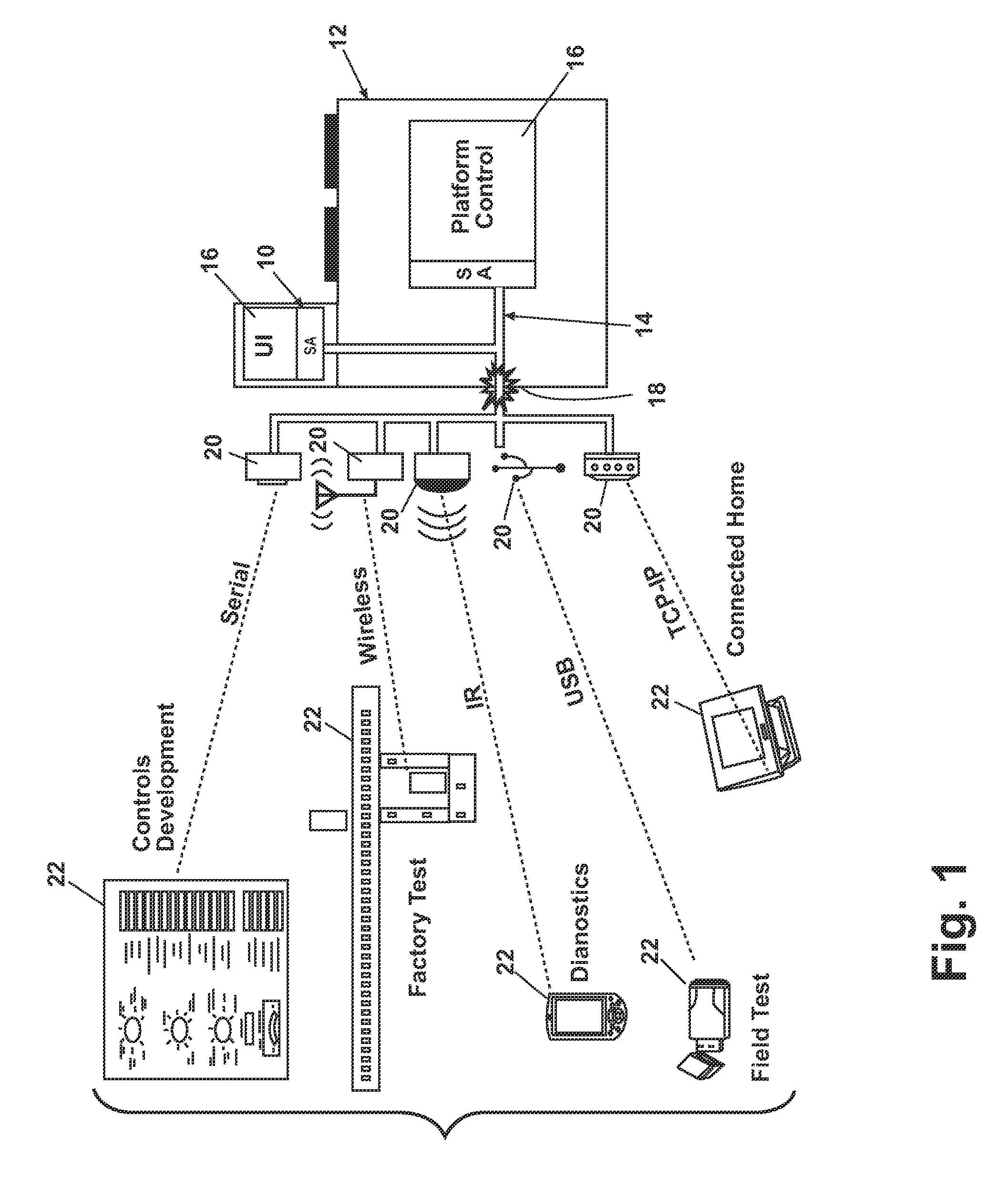
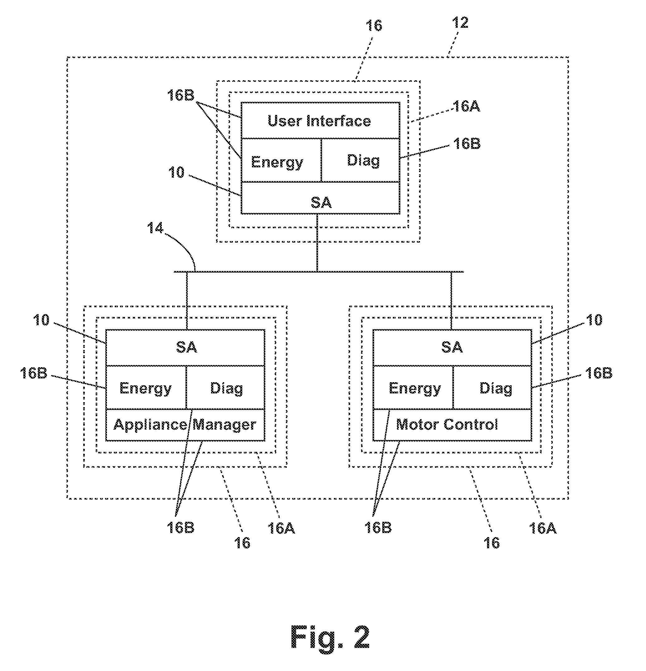
[0060]A brief overview of the invention should be helpful before examining the multiple aspects of the invention. The invention relates to a software architecture (“SA”) that is implemented on and communicates over an internal communications network on an appliance, which connects the various physical components of the appliance.

[0061]Some of the physical components have a corresponding controller (main controller, motor controller, user interface, etc.), which may be a simple microprocessor mounted on a printed circuit board. Other components have no controller. Typically the components that have controllers (and if there are more than one are typically also network enabled) cooperate through network messaging or other forms of data transmission to directly or indirectly, through other components, control the operation of all of the components and their contained or attached devices to implement an operation or cycle for the appliance.

[0062]The SA can, but does not have to, reside ...


PUM


Abstract

A system comprising a memory heap generated dynamically by useful software and a data acquisition engine. The memory heap comprises a plurality of event structures, each including at least one each of pointers into memory external to the event structure, event operators, and arguments. The data acquisition engine is configured to look into the memory heap, evaluate event conditions as true or false based on the at least one each of the pointers, operators, and arguments, and generate a notification message when a true condition is found.

Description

CROSS-REFERENCE TO RELATED APPLICATIONS[0001]This application is a continuation of International Application No. PCT / US06 / 22420, filed Jun. 8, 2006, which claims the benefit of U.S. Patent Application No. 60 / 595,148, filed Jun. 9, 2005, whose disclosure is incorporated by reference.BACKGROUND OF THE INVENTION[0002]1. Field of the Invention[0003]The invention relates to a data acquisition engine and system for an appliance.[0004]2. Description of the Related Art[0005]Household appliances are typically comprised of one or more components which cause the electromechanical, electrothermal, and electrochemical operations of the appliance. For example, an oven may include an appliance management component, having a printed circuit board (PCB) with memory thereon, as well as a user interface component, such as a control panel or keypad for a user to issue commands to the oven appliance. The basic appliance models typically are difficult to design, develop, test, diagnose, control, and debu...

Claims


Application Information

Patent Timeline
Patent Type & Authority Patents(United States)
IPC IPC(8): G06F9/44G06F15/16G05B9/02
CPCH04L12/2816H04L12/2825H04L69/26H04L67/12H04L2012/285
Inventor MCCOY, RICHARD A.CARROLL, JOSHUA P.EBROM, MATTHEW P.PUTNAM, DANIEL M.KMET, DAVID J.WHIPPLE, ANDREW D.GLOTZBACH, PATRICK J.
Owner WHIRLPOOL CORP
Learn More