
System and method for improving the distortion tolerance of an electromagnetic tracking system

a technology of electromagnetic tracking system and distortion tolerance, which is applied in the field of electromagnetic tracking system, can solve the problems of electromagnetic tracking system distortion, electromagnetic tracking system accuracy degradation,

Active Publication Date: 2011-03-22
NORTHERN DIGITAL
View PDF14 Cites 40 Cited by
  • Summary
  • Abstract
  • Description
  • Claims
  • Application Information

AI Technical Summary

Benefits of technology

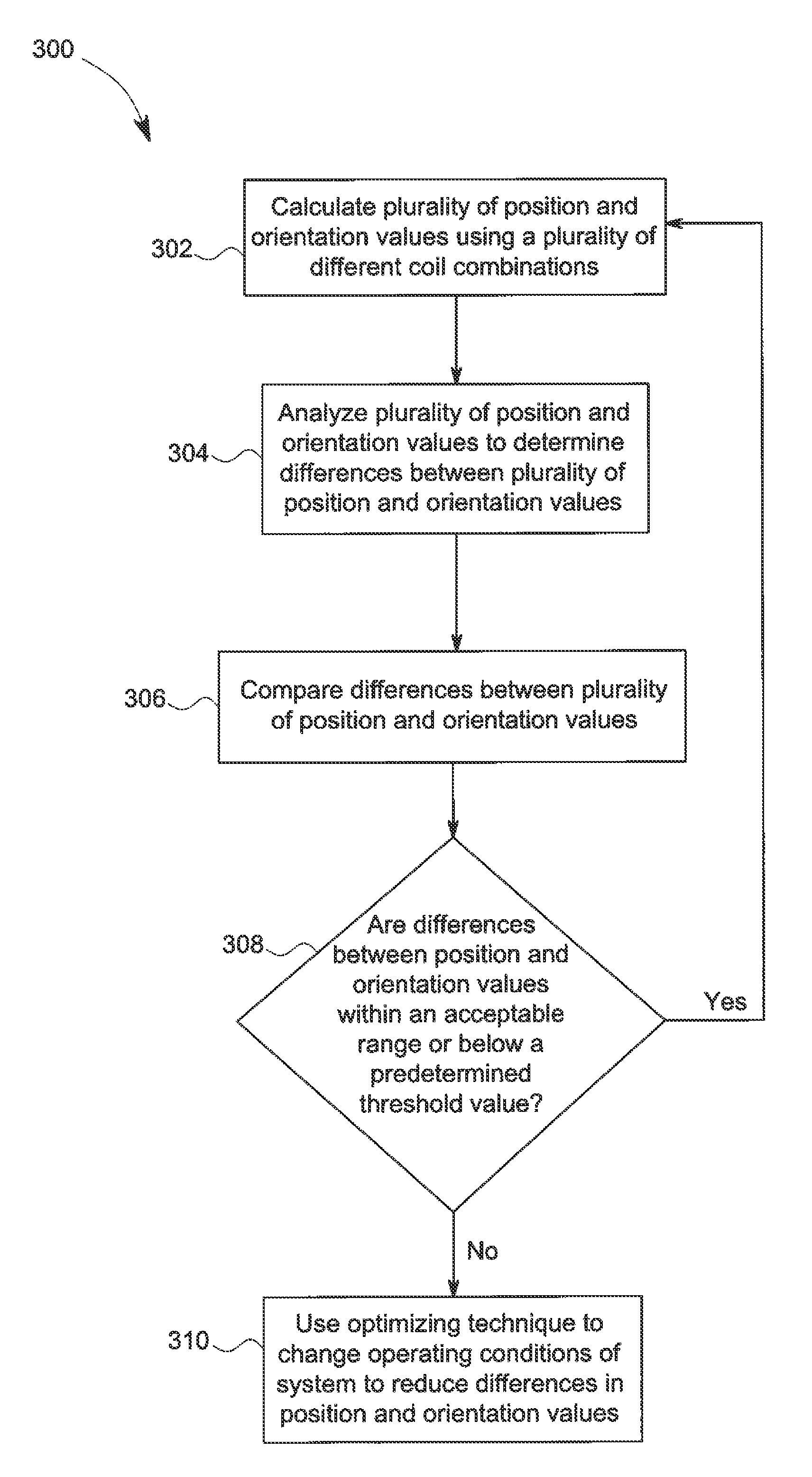
[0007]In an exemplary embodiment, a method of improving the distortion tolerance of an electromagnetic tracking system, the method comprising calculating a plurality of position and orientation values using a plurality of different coil combinations; analyzing the plurality of position and orientation values to determine differences between the plurality of position and orientation values; and using an optimizing technique to change the operating conditions of the electromagnetic tracking system to reduce the differences between the plurality of position and orientation values.
[0008]In an exemplary embodiment, a method of improving the distortion tolerance of an electromagnetic tracking system, the method comprising calculating a plurality of position and orientation values using a plurality of different coil combinations; calculating a distortion indicator; comparing the distortion indicator to the differences between the plurality of position and orientation values; and using an optimizing technique to change the operating conditions of the electromagnetic tracking system when the distortion indicator is greater than a predetermined threshold value to reduce the differences between the plurality of position and orientation values.
[0009]In an exemplary embodiment, a method of improving the distortion tolerance of an electromagnetic tracking system, the method comprising determining a set of optimal transmitter frequencies in real-time for use by the electromagnetic tracking system; and using the set of optimal transmitter frequencies to reduce the distortion caused by a distorter within the tracking volume.
[0010]In an exemplary embodiment, a method of improving the distortion tolerance of an electromagnetic tracking system, the method comprising calculating a plurality of position and orientation values using a plurality of different transmitter frequencies; analyzing the plurality of position and orientation values to determine differences between the plurality of position and orientation values; and using an optimizing technique to change the operating conditions of the electromagnetic tracking system to reduce the differences between the plurality of position and orientation values.
[0011]In an exemplary embodiment, a method of improving the distortion tolerance of an electromagnetic tracking system, the method comprising calculating a plurality of position and orientation values using a plurality of different coil combinations; analyzing the plurality of position and orientation values to determine differences between the plurality of position and orientation values; and removing a particular coil or coils from a coil set to reduce the level of disagreement between the plurality of position and orientation values when there are multiple position and orientation values from the set and a particular coil or coils is used repeatedly in position and orientation values that are above an acceptable range of position and orientation values or above a predetermined threshold value.

Problems solved by technology

However, electromagnetic tracking systems are known to suffer from accuracy degradation due to electromagnetic field distortion caused by the presence of an uncharacterized metal distorter within the tracking volume or electromagnetic fields of the electromagnetic tracking system.
The presence of an uncharacterized metal distorter within the tracking volume of the electromagnetic tracking system may create distortion of the electromagnetic fields of the electromagnetic tracking system.
This distortion may cause inaccuracies in tracking the position and orientation of medical devices and instruments by causing inaccuracies in position and orientation calculations of the coils of the electromagnetic transmitter relative to the coils of the electromagnetic receiver, or the coils of the electromagnetic receiver relative to the coils of the electromagnetic transmitter.

Method used


Image

  • System and method for improving the distortion tolerance of an electromagnetic tracking system
  • System and method for improving the distortion tolerance of an electromagnetic tracking system
  • System and method for improving the distortion tolerance of an electromagnetic tracking system

Examples


Embodiment Construction

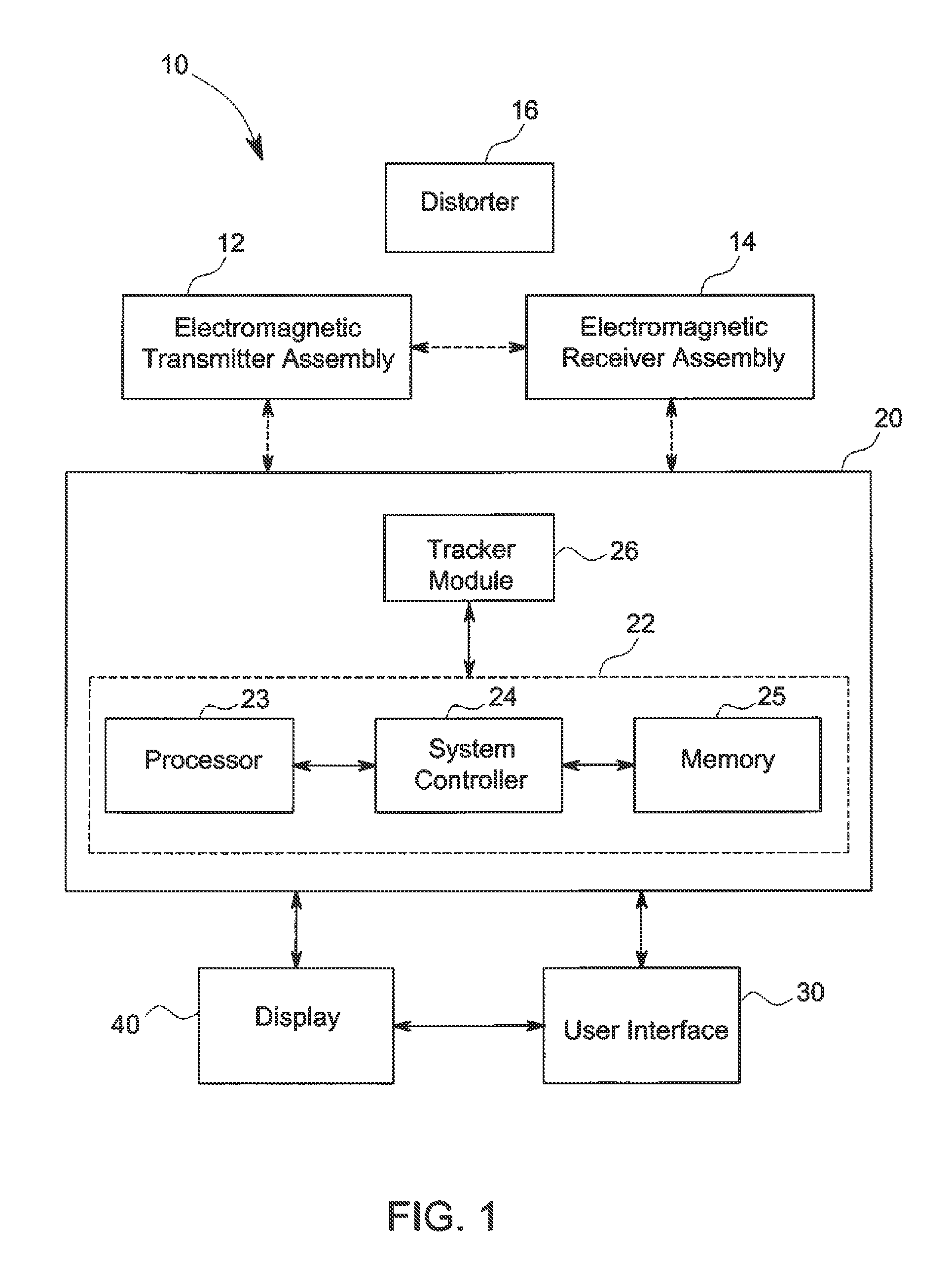
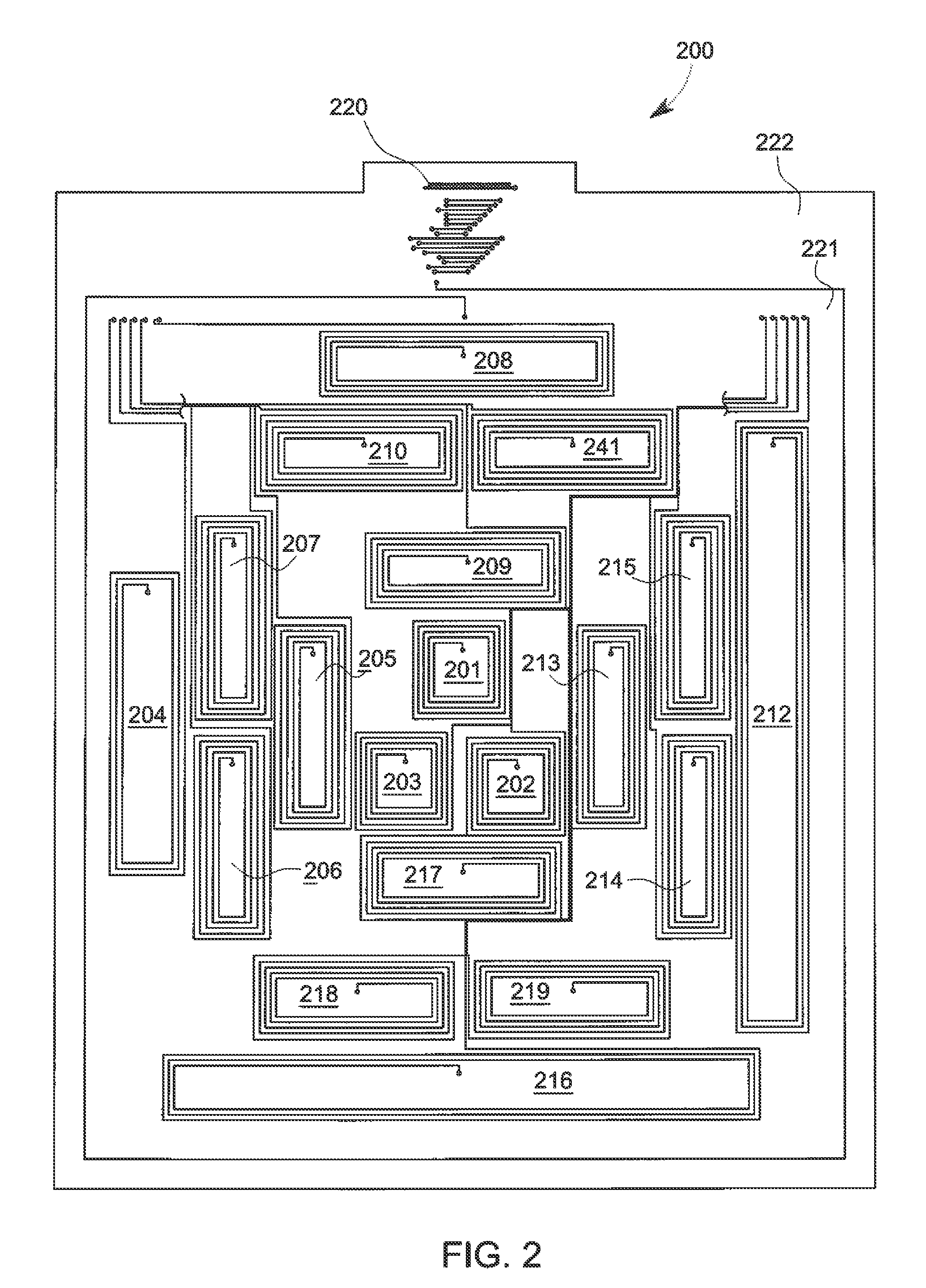
[0017]Referring now to the drawings, FIG. 1 is a block diagram illustrating an exemplary embodiment of an electromagnetic tracking system 10. The electromagnetic tracking system 10 comprises at least one electromagnetic transmitter assembly 12 with a set of one or more coils or a coil array, and at least one electromagnetic receiver assembly 14 with a set of one or more coils or a coil array. The electromagnetic tracking system 10 provides position and orientation data that spatially relate one or more coils, sets of coils, subsets of coils with one or more other coils, sets of coils, subsets of coils. Each of the coils in each set of coils or subset of coils is positioned in a fixed manner relative to each other, such as within the same housing. In an exemplary embodiment, none of the one or more coils of the electromagnetic transmitter assembly 12 transmit on the same frequency at the same time to avoid self-interference.

[0018]FIG. 1 also illustrates at least one distorter 16 with...


PUM


Abstract

A system and method for improving the tolerability of metal distorters within the electromagnetic field of an electromagnetic tracking system through the use of transmission frequency optimization techniques and / or solution subset measurements.

Description

BACKGROUND OF THE INVENTION[0001]This disclosure relates generally to an electromagnetic tracking system that uses electromagnetic fields to determine the position and orientation of an object, and more particularly to a system and method for improving the distortion tolerance of an electromagnetic tracking system.[0002]Electromagnetic tracking systems have been used in various industries and applications to provide position and orientation information relating to objects. For example, electromagnetic tracking systems may be useful in aviation applications, motion sensing applications, retail applications, and medical applications. In medical applications, electromagnetic tracking systems have been used to provide an operator (e.g., a physician, surgeon, or other medical practitioner) with information to assist in the precise and rapid positioning of a medical device or instrument located in or near a patient's body during image-guided surgery. An electromagnetic tracking system pro...

Claims


Application Information

Patent Timeline
Patent Type & Authority Patents(United States)
IPC IPC(8): G01D18/00G01C17/00
CPCA61B5/062A61B2017/00725A61B34/20A61B2034/2051G01B7/003
Inventor ZUHARS, JOEL FREDERICKCHANDONNET, JASON RENE
Owner NORTHERN DIGITAL
Learn More