
Methods and systems to monitor venous blood oxygen saturation

a technology of venous blood oxygen and monitoring system, which is applied in the field of implantable cardiac stimulation devices, can solve the problems of increasing the battery life of the device, reducing the longevity of such devices, and adding to the cost and complexity of implantable cardiac systems

Inactive Publication Date: 2011-03-22
PACESETTER INC
View PDF7 Cites 10 Cited by
  • Summary
  • Abstract
  • Description
  • Claims
  • Application Information

AI Technical Summary

Benefits of technology

[0005]In accordance with specific embodiments, the above steps are repeated over time to thereby monitor changes in the patient's SvO2 over time. This can include interpreting increases in T-wave metrics and/or PR intervals as increases in the patient's SvO2, and interpreting decreases in such metrics as decreases in the patient's SvO2. Based on such monitored changes in SvO2, pacing rate and pacing interval optimization, or more generally pacing rate and pacing interval adjustments, can be performed. In other words, measures of SvO2, as determined from an IEGM and/or ECG, can be used as a measure of hemodynamic response in a pacing adjustment or optimization algorithm.
[0006]In accordance with further embodiments, changes in a patient's SvO2, as measured based on changes in metric(s) of a signal indicative of electrical activity of the patient's heart, can be used to monitor changes in a patient's heart failure (HF) condition. This can include interpreting decreases in the patient's SvO2 over time as being indicative of worsening of the patient's heart failure, and interpreting increases in the patient's SvO2 over time as being indicative of improvement of the patient's heart failure.
[

Problems solved by technology

While such optical sensors are useful, they may add to the cost and complexity of implantable cardiac systems.
Additionally, such optical sensors may cause an increased drain on device batteries, potentially reducing the longevity of such devices.

Method used


Image

  • Methods and systems to monitor venous blood oxygen saturation
  • Methods and systems to monitor venous blood oxygen saturation
  • Methods and systems to monitor venous blood oxygen saturation

Examples


Embodiment Construction

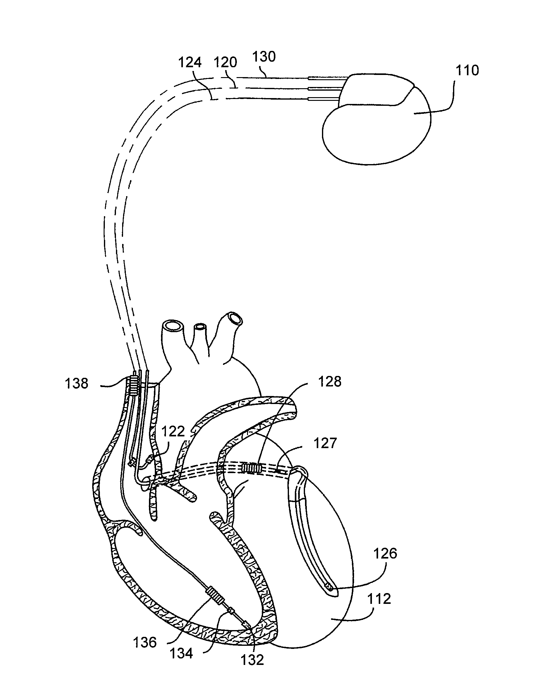
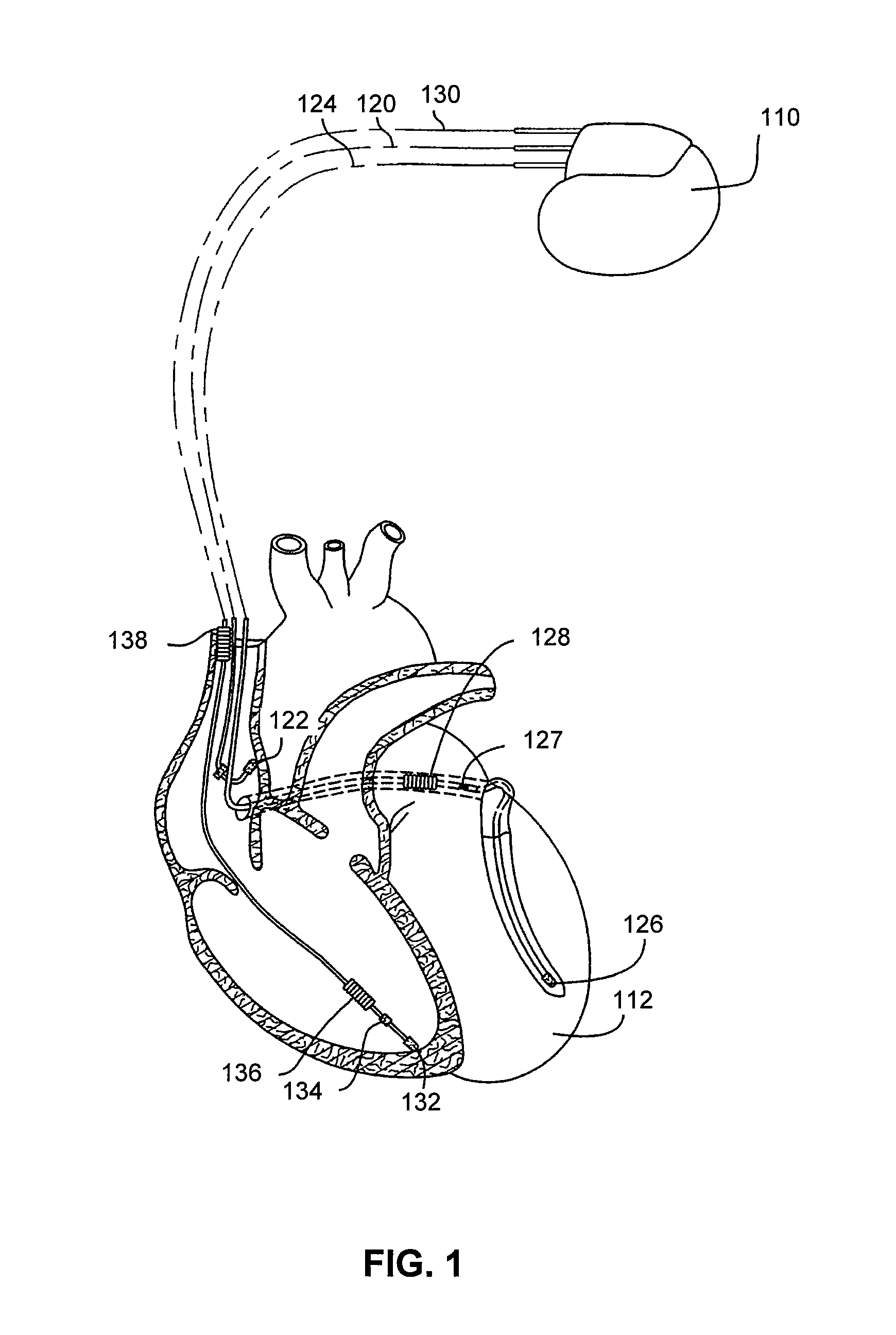
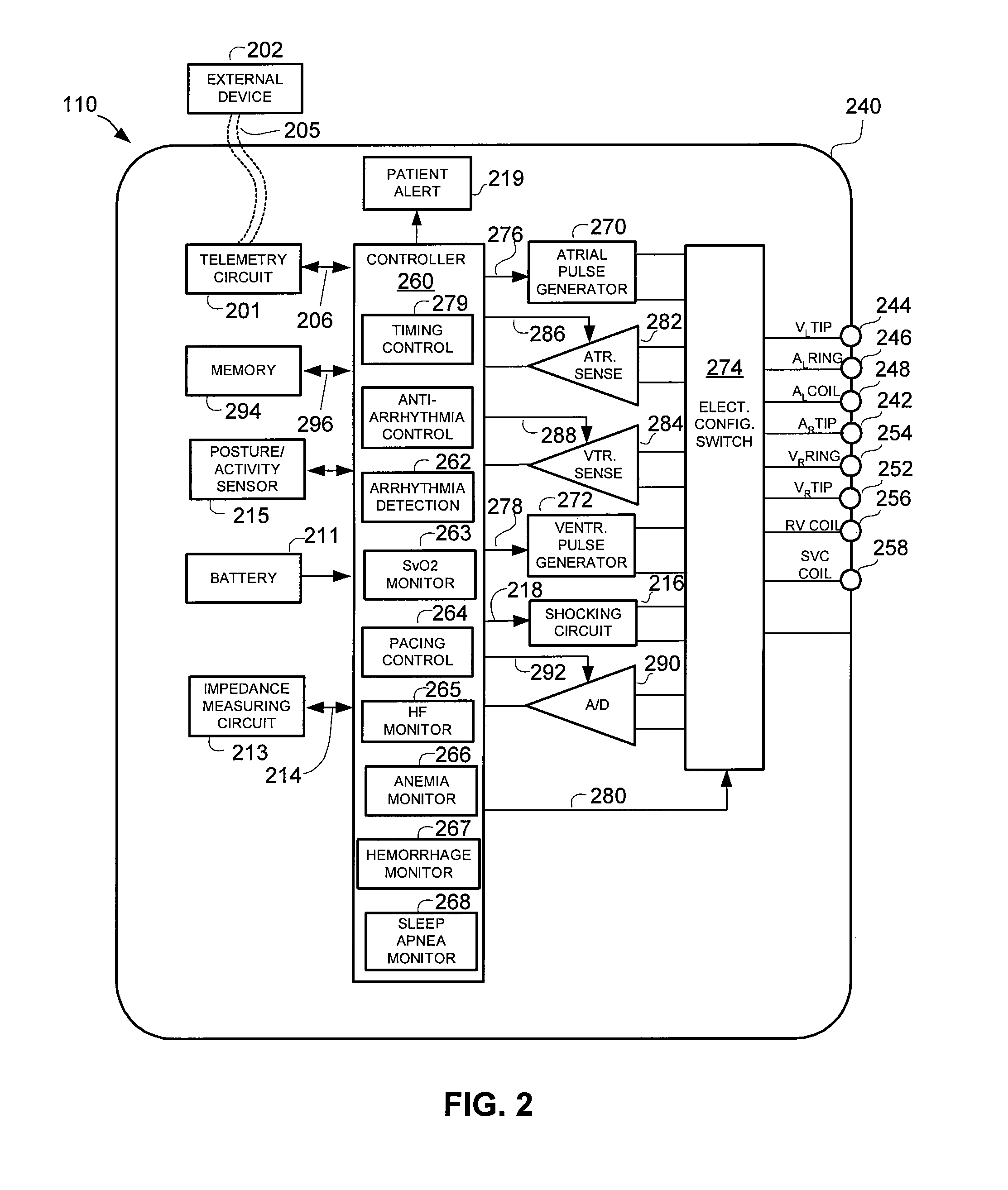
[0023]The following description is of the best modes presently contemplated for practicing various embodiments of the present invention. The description is not to be taken in a limiting sense but is made merely for the purpose of describing the general principles of the invention. The scope of the invention should be ascertained with reference to the claims. In the description of the invention that follows, like numerals or reference designators will be used to refer to like parts or elements throughout. In addition, the first digit of a reference number identifies the drawing in which the reference number first appears.

[0024]The disclosed systems and methods of the present invention generally relate to using an intracardiac electrogram (IEGM) and / or an electrocardiogram (ECG) to monitor a patient's venous blood oxygen saturation. While its possible and within the scope of the present invention to employ techniques of the present invention in an external (i.e., non-implantable) syst...


PUM


Abstract

Methods and system are provided for monitoring a patients venous blood oxygen saturation (SvO2). At least one signal indicative of electrical activity of a patient's heart is obtained. Such a signal can be, e.g., an IEGM or ECG signal. In specific embodiments, such a signal(s) can be obtained from implanted electrodes, and thus, embodiments of the present invention can be implemented by an implantable system. Additionally, there are measurements of at least one metric of cardiac cycles represented in the at least one signal indicative of electrical activity of the patient's heart, where the metric changes with changes in SvO2. Examples of such metric include T-wave metrics and PR intervals. SvO2, and changes therein, are monitored based on the measured metric(s).

Description

FIELD OF THE INVENTION[0001]The present invention relates generally to implantable cardiac stimulation devices capable of monitoring venous oxygen saturation (SvO2) using an intracardiac electrogram (IEGM) or electrocardiogram (ECG).BACKGROUND OF THE INVENTION[0002]Implantable cardiac stimulation devices are currently being used to treat various types of arrhythmias, such as ventricular tachycardia (VT) and ventricular fibrillation (VF). Such devices are capable of detecting the occurrence of an arrhythmia, and automatically applying an appropriate electrical stimulation or shock therapy to the heart aimed at terminating the detected arrhythmia. In addition to providing automatic stimulation, such devices often include circuitry that is configured to acquire intracardiac electrogram (IEGM) signals, convert the raw analog data into digital signals, and store the digital signals for later processing and / or telemetric transmission to an external device.[0003]Recently there has been inc...

Claims


Application Information

Patent Timeline
IPC IPC(8): A61B5/00A61B5/04
CPCA61B5/0452A61B5/14542A61N1/36557A61B5/349A61B5/36A61B5/355
Inventor WENZEL, BRIAN JEFFREYQU, FUJIANFARAZI, TARANEH GHAFFARI
Owner PACESETTER INC
Learn More