Image recording apparatus
a recording apparatus and image technology, applied in printing and other directions, can solve problems such as contamination of conveyor belts or paper, and achieve the effect of suppressing contamination of recording mediums and/or recording medium conveyance mechanisms
- Summary
- Abstract
- Description
- Claims
- Application Information
AI Technical Summary
Benefits of technology
Problems solved by technology
Method used
Image

Examples
first embodiment
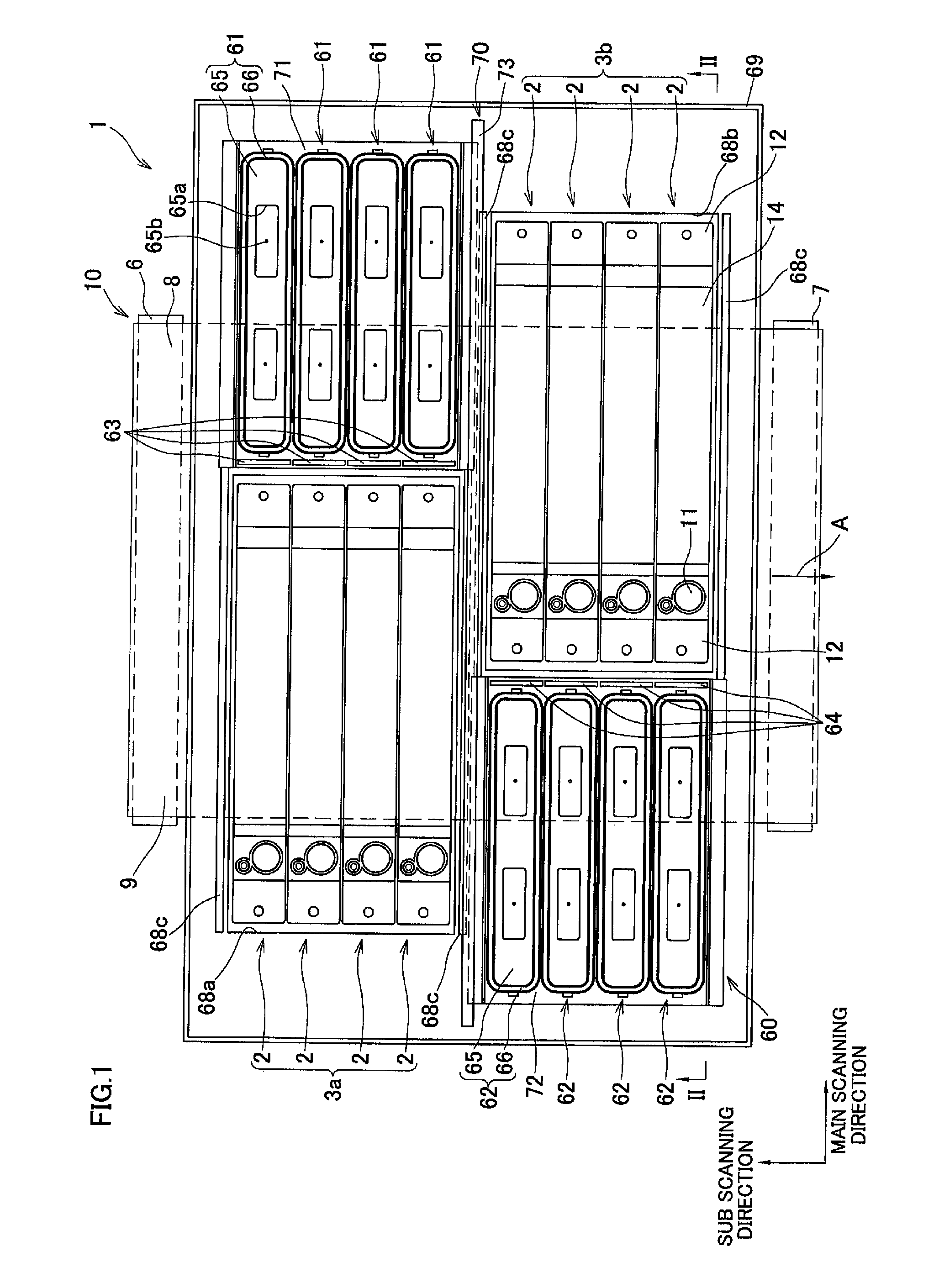
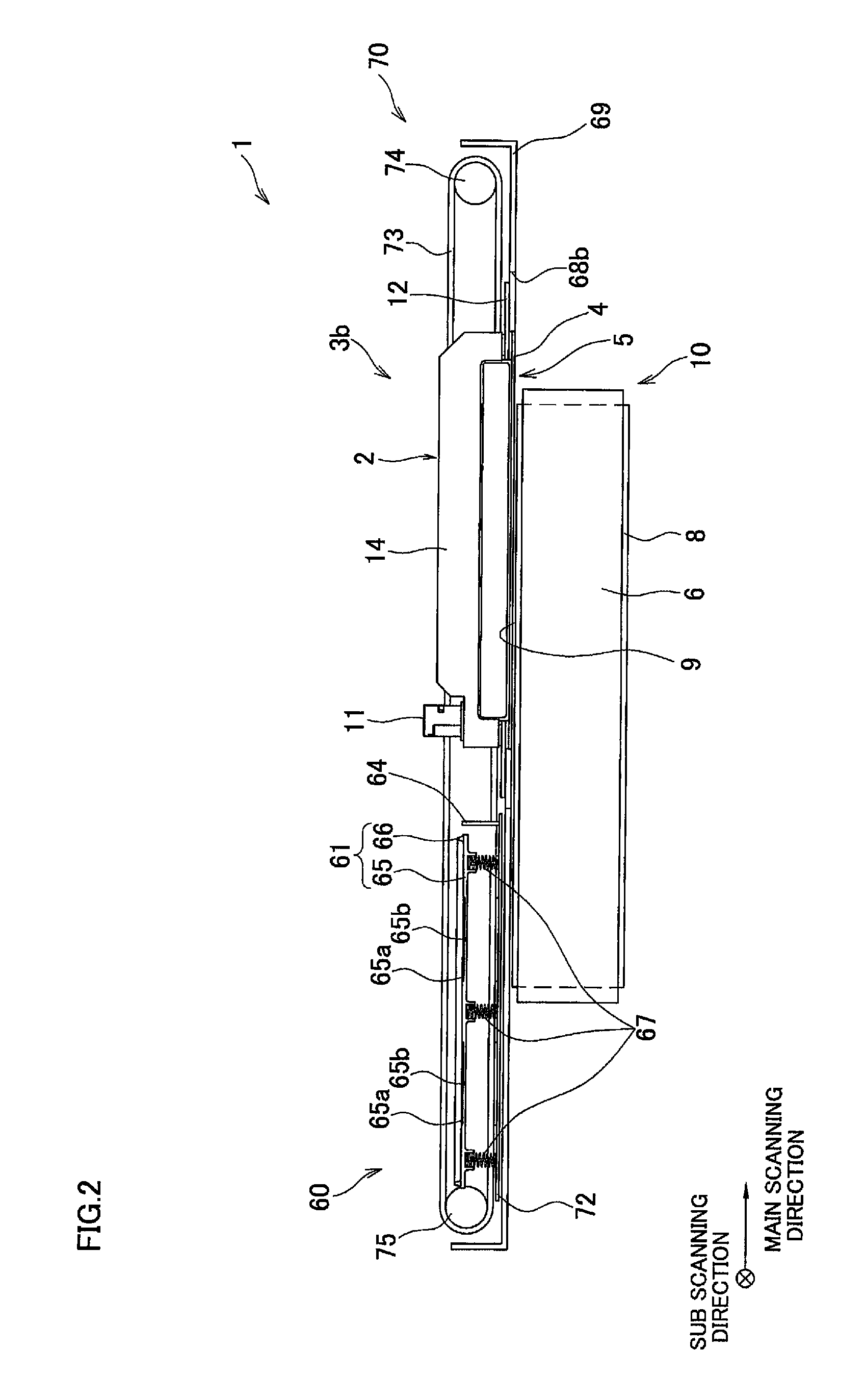
[0020]FIG. 1 is a plan view of an essential part of an ink-jet printer according to the present invention. FIG. 2 is a sectional view as taken along line II-II illustrated in FIG. 1. FIG. 3 shows two head groups illustrated in FIG. 1, as seen from a bottom side thereof.
[0021]As shown in FIG. 1, an ink-jet printer 1, which is an image recording apparatus of this embodiment, is a color ink-jet printer of line type including two head groups 3a and 3b each of which is made up of four ink-jet heads 2 or liquid ejection heads. The ink-jet printer 1 has a paper feed unit (not shown) and a paper discharge unit (not shown) at upper and lower parts of FIG. 1, respectively.
[0022]In the ink-jet printer 1, a paper conveyance mechanism 10 which is a recording medium conveyance mechanism is provided between the paper feed unit and the paper discharge unit, at a position opposed to the two head groups 3a and 3b. The paper conveyance mechanism 10 conveys a paper as a recording medium to a position o...
second embodiment
[0100]In this way, it is possible to move the three support plates 472 to 474 each of which supports two caps 461 (or 462) and two wipers 463 (or 464) associated with two ink-jet heads 402. In addition, as compared with in the second embodiment, a less number of portions of the belt 476 extending in the main scanning direction are positioned between neighboring ink-jet heads 402, which can simplify the structure of the movement mechanism 470.
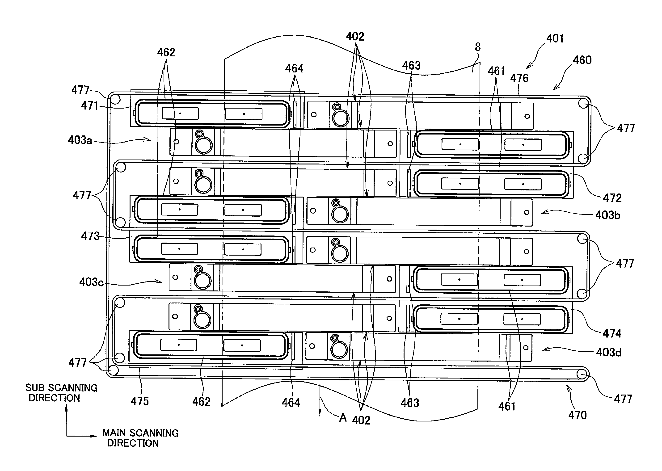
[0101]With the maintenance unit 460 having the above-described structure, when the drive motor 95 rotates one (upper left one in FIG. 8) roller 477 in the clockwise direction in FIG. 8, the four caps 461 and the four wipers 463 mounted on the two support plates 472 and 474 move together with the support plates 472 and 474 from the withdrawal position (as shown in FIG. 8), leftward in FIG. 8 along the main scanning direction, while the four caps 462 and the four wipers 464 mounted on the three support plates 471, 473, and 475 move together with t...
fourth embodiment
[0114]The two ink-jet heads 502 belonging to each of the head groups 503a, 503b, 503c, and 503d have their ink ejection faces 4 overlap each other along the sub scanning direction, which is the same in the The four head groups 503a, 503b, 503c, and 503d eject ink of different colors. In this embodiment, the three head groups 503a, 503b, and 503c eject black ink, magenta ink, and cyan ink, while the head group 503d ejects yellow ink.
[0115]The maintenance unit 560 has eight caps 561 and 562, eight wipers 563 and 564, and a movement mechanism 570. The eight caps 561 and 562, and the eight wipers 563 and 564 correspond to the eight ink-jet heads 502, respectively. The movement mechanism 570 moves the respective caps 561, 562 and the respective wipers 563, 564 in the main scanning direction.
[0116]The movement mechanism 570 has eight rollers 577, one belt 576 which spans the rollers 577, and four support plates 571 to 574 coupled with the belt 576. The eight rollers 577 are arranged in s...
PUM
 Abstract
Description
Claims
Application Information
 - R&D
- Intellectual Property
- Life Sciences
- Materials
- Tech Scout
- Unparalleled Data Quality
- Higher Quality Content
- 60% Fewer Hallucinations
Browse by: Latest US Patents, China's latest patents, Technical Efficacy Thesaurus, Application Domain, Technology Topic, Popular Technical Reports.
© 2025 PatSnap. All rights reserved.Legal|Privacy policy|Modern Slavery Act Transparency Statement|Sitemap|About US| Contact US: help@patsnap.com