Image display device

a technology of image display and display screen, which is applied in the direction of television systems, signals with optical-mechanical scanning, instruments, etc., can solve the problems of blurry visual perception of borders with different display brightness, achieve the effect of improving the display performance of moving images, and suppressing the occurrence of any moving image blur

Inactive Publication Date: 2011-03-08
SHARP KK
View PDF9 Cites 3 Cited by
  • Summary
  • Abstract
  • Description
  • Claims
  • Application Information

AI Technical Summary

Benefits of technology

[0028]According to the first aspect of the present invention, the overshoot process circuit is provided at the subsequent stage of the time-division gradation process circuit, and time-division gradation drive and overshoot drive are performed. Time-division gradation drive makes it possible to suppress occurrence of any moving image blur, and overshoot drive makes is possible to make up for a lack of response speed of the display elements. Accordingly, it is possible to improve moving image display performance, while making up for the lack of response speed of the display elements.
[0029]According to the second aspect of the present invention, a predetermined-times higher speed process is performed on an input video signal to obtain a video signal in units of sub-frames. Accordingly, by suppressing occurrence of any moving image blur via time-division gradation drive, and making up for a lack of response speed of the display elements via overshoot drive, it becomes possible to improve moving image display performance, while making up for the lack of response speed of the display elements.
[0030]According to the third aspect of the present invention, a frame interpolation process and a predetermined-times higher speed process are performed on an input video signal to obtain a video signal in units of sub-frames. Accordingly, by suppressing occurrence of any moving image blur via the frame interpolation process and time-division gradation drive, and making up for a lack of response speed of the display elements via overshoot drive, it becomes possible to improve moving image display performance, while making up for the lack of response speed of the display elements.
[0031]According to the fourth aspect of the present invention, a frame interpolation process is performed on an input video signal to obtain a video signal in units of sub-frames. Accordingly, by suppressing occurrence of any moving image blur via the frame interpolation process and time-division gradation drive, and making up for a lack of response speed of the display elements via overshoot drive, it becomes possible to improve moving image display performance, while making up for the lack of response speed of the display elements.
[0032]According to the fifth aspect of the present invention, by selectively operating the video processing circuit and the time-division gradation process circuit using a control signal, it is possible to switch between modes of driving the display elements. In addition, the overshoot process circuit is provided for performing a different type of gradation level conversion in accordance with the control signal, and therefore it is possible to eliminate the need to provide an overshoot process circuit for each drive mode, resulting in a reduction in the cost of the image display device.
[0033]According to the sixth aspect of the present invention, by performing gradation level conversion after the time-division gradation process, such that brightness of the display elements after one sub-frame cycle corresponds to the pre-conversion gradation level of the video signal, it becomes possible to control the brightness of the display elements to be at a desired level after one sub-frame cycle, thereby making up for a lack of response speed of the display elements.

Problems solved by technology

Image display devices, such as liquid crystal display devices, are disadvantageous in that, when displaying a moving image, boundaries with different display brightness are visually perceived as blurry.

Method used


Image

  • Image display device
  • Image display device
  • Image display device

Examples


first embodiment

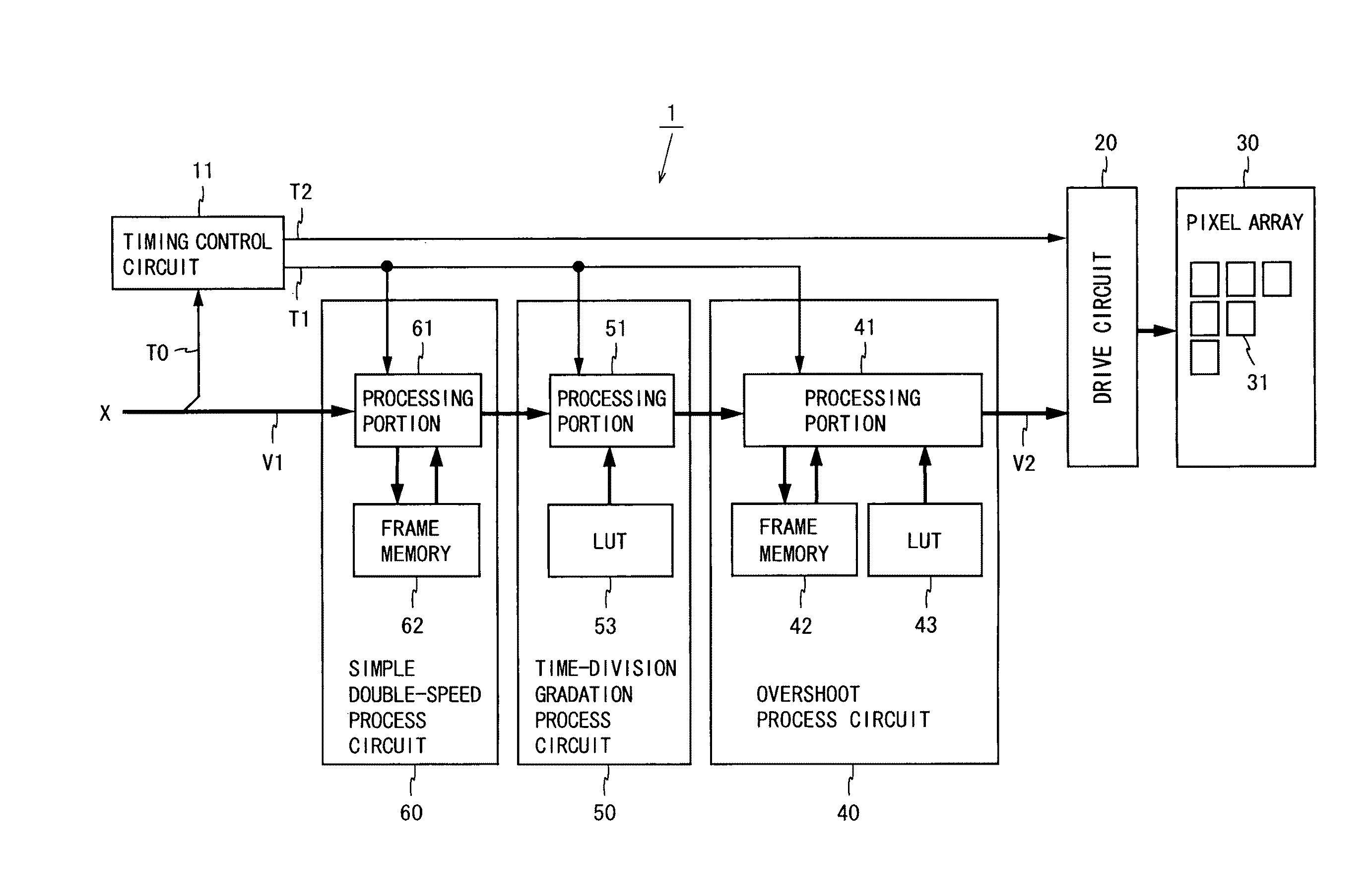
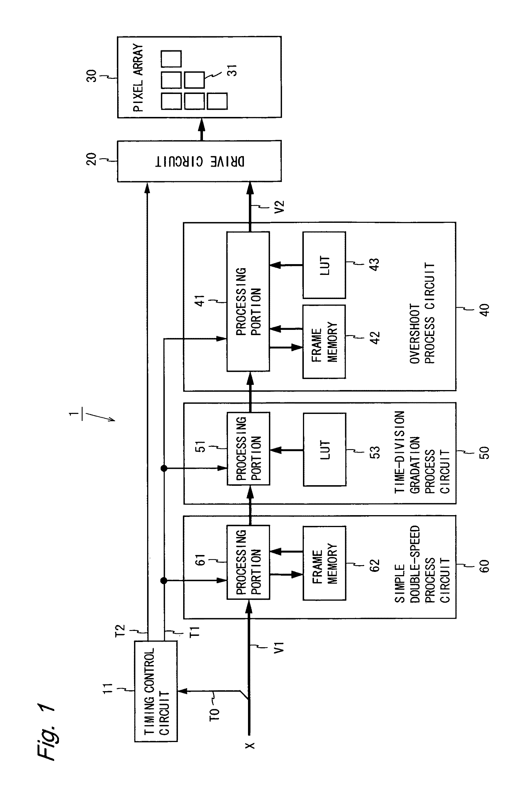
[0081]FIG. 1 is a block diagram illustrating the configuration of a liquid crystal display device according to a first embodiment of the present invention. The liquid crystal display device 1 shown in FIG. 1 includes a timing control circuit 11, a drive circuit 20, a pixel array 30, an overshoot process circuit 40, a time-division gradation process circuit 50, and a simple double-speed process circuit 60. The liquid crystal display device 1 performs three processes (a simple double-speed process, a time-division gradation process, and an overshoot process) on a video signal V1, and provides a gradation display using a resultant video signal V2. In the present embodiment, the simple double-speed process circuit 60 constitutes a video conversion circuit for obtaining a video signal in units of sub-frames based on a video signal inputted in units of frames.

[0082]An input signal X to be supplied to the liquid crystal display device 1 includes the video signal V1 representing image data,...

second embodiment

[0109]FIG. 12 is a block diagram illustrating the configuration of a liquid crystal display device according to a second embodiment of the present invention. The liquid crystal display device 2 shown in FIG. 12 includes a timing control circuit 12, a drive circuit 20, a pixel array 30, an overshoot process circuit 40, a time-division gradation process circuit 50, a simple double-speed process circuit 60, and a frame interpolation process circuit 70. The liquid crystal display device 2 performs four processes (a frame interpolation process, a simple double-speed process, a time-division gradation process, and an overshoot process) on a video signal V1, and provides a gradation display using a resultant video signal V2. In the present embodiment, the simple double-speed process circuit 60 and the frame interpolation process circuit 70 constitute a video conversion circuit for obtaining a video signal in units of sub-frames based on a video signal inputted in units of frames. In the pr...

third embodiment

[0119]FIG. 18 is a block diagram illustrating the configuration of a liquid crystal display device according to a third embodiment of the present invention. The liquid crystal display device 3 shown in FIG. 18 includes a timing control circuit 13, a drive circuit 20, a pixel array 30, an overshoot process circuit 40, a time-division gradation process circuit 50, and a frame interpolation process circuit 70. The liquid crystal display device 3 performs three processes (a frame interpolation process, a time-division gradation process, and an overshoot process) on a video signal V1, and displays a screen based on a resultant video signal V2. In the present embodiment, the frame interpolation process circuit 70 constitutes a video conversion circuit for obtaining a video signal in units of sub-frames based on a video signal inputted in units of frames. In the present embodiment, the same elements as those in the above-described embodiments are denoted by the same reference characters, a...


PUM


Abstract

A simple double-speed process circuit 60 outputs a video signal V1 twice at a double speed in units of frames. A time-division gradation process circuit 50 performs gradation level conversion on the video signal in order to distribute brightness for one frame cycle to two sub-frame cycles, i.e. first and second sub-frame cycles. An overshoot process circuit 40 performs gradation level conversion on the video signal in order to-emphasize a temporal change of the signal. A drive circuit 20 drives liquid crystal display elements 31 using a video signal V2 obtained through processing by the three circuits. A frame interpolation process circuit may be added to this circuit configuration or may be substituted for the simple double-speed process circuit 60. This makes it possible to improve moving image display performance, while making up for a lack of response speed of the display elements.

Description

TECHNICAL FIELD[0001]The present invention relates to image display devices, such as liquid crystal display devices and electroluminescence display devices.BACKGROUND ART[0002]Image display devices, such as liquid crystal display devices, are disadvantageous in that, when displaying a moving image, boundaries with different display brightness are visually perceived as blurry. Such a deterioration in moving image display performance is due to the following two factors. The first factor is that display elements have a response speed slower than a speed corresponding to one frame cycle of video. A known technology for making up for such a lack of response speed of the display elements is overshoot drive (also referred to as “overdrive”). Overshoot drive is a method for forcibly driving display elements at high speed by applying voltage higher or lower than voltage for achieving a desired gradation level, in accordance with the direction in which the gradation level of a video signal ch...

Claims


Application Information

Patent Timeline
Patent Type & Authority Patents(United States)
IPC IPC(8): G09G5/10
CPCG09G3/3688G09G2320/0252G09G2320/106G09G2340/0435G09G2340/16
Inventor INOUE, AKIHIKO
Owner SHARP KK
Why Eureka
Try Eureka