Quasi-resonant fly-back converter without auxiliary winding

a fly-back converter and quasi-resonant technology, applied in the direction of electric variable regulation, process and machine control, instruments, etc., can solve the problems of increasing manufacturing cost, and achieve the effect of low/minimized switching loss, switching noise and manufacturing cos

Active Publication Date: 2011-03-01
LEADTREND TECH
View PDF3 Cites 35 Cited by
  • Summary
  • Abstract
  • Description
  • Claims
  • Application Information

AI Technical Summary

Benefits of technology

[0008]Therefore, one objective of the present invention is to provide a switching converter, which can detect the demagnetization of the transformer of the switching converter without utilizing an auxiliary winding and a complicated detection circuit. Hence, the present invention can provide a voltage converting function with low / minimized switching loss, switching noise and manufacturing cost.

Problems solved by technology

The auxiliary winding LB, however, represents an additional element that increases manufacturing cost.

Method used


Image

  • Quasi-resonant fly-back converter without auxiliary winding
  • Quasi-resonant fly-back converter without auxiliary winding
  • Quasi-resonant fly-back converter without auxiliary winding

Examples


Embodiment Construction

[0015]Certain terms are used throughout the following description and claims to refer to particular system components. As one skilled in the art will appreciate, manufacturers may refer to a component by different names. This document does not intend to distinguish between components that differ in name but not function. In the following discussion and in the claims, the terms “including” and “comprising” are used in an open-ended fashion, and thus should be interpreted to mean “including, but not limited to . . . ” The terms “couple” and “couples” are intended to mean either an indirect or a direct electrical connection. Thus, if a first device couples to a second device, that connection may be through a direct electrical connection, or through an indirect electrical connection via other devices and connections.

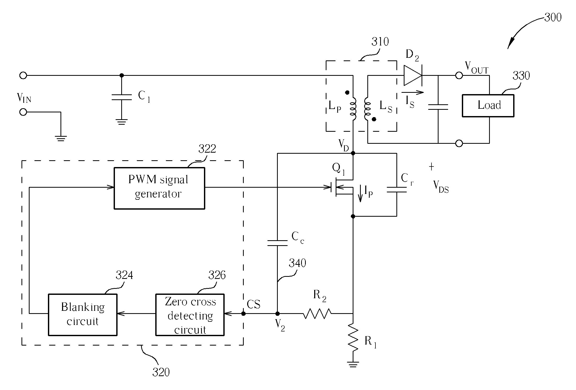
[0016]Please refer to FIG. 3, which is a diagram of a quasi-resonant fly-back converter according to an exemplary embodiment of the invention. The quasi-resonant fly-back co...


PUM


Abstract

Disclosed is a switching converter without an auxiliary winding. The switching converter has a transformer, a switching transistor, a coupling circuit and a regulating circuit. The transformer has a primary winding and a secondary winding, and is for transforming an input voltage into an output voltage; a first end of the switching transistor is coupled to the primary winding of the transformer, and the switching transistor is for controlling an operation of the transformer according to a control signal; the coupling circuit is for coupling a signal at the first end of the switching transistor to generate a coupled signal; and the regulating circuit is for detecting the coupled signal to generate the control signal according to the detecting result.

Description

BACKGROUND OF THE INVENTION[0001]1. Field of the Invention[0002]The invention relates to a power converter, and more particularly, to a switching converter that reduces switching loss without an auxiliary winding implemented.[0003]2. Description of the Prior Art[0004]FIG. 1 illustrates a conventional quasi-resonant fly-back converter, capable of reducing switching loss and switching noise. The converter 100 shown in FIG. 1 includes a transformer T having a primary winding LP and a secondary winding LS, and a power switching transistor Q1 coupled to the primary winding LP of the transformer T. When the power switching transistor Q1 is on, the input energy of the converter 100 originating from the input voltage VIN at the input end is stored into the transformer T, and when the power switching transistor Q1 is off, the energy stored in the transformer T is transferred to the output end, forming a DC output voltage VOUT at the load 101. The switching operation of the power switching tr...

Claims


Application Information

Patent Timeline
Patent Type & Authority Patents(United States)
IPC IPC(8): H02M3/335
CPCH02M1/40H02M3/33523H02M2001/0009Y02B70/1433Y02B70/10H02M1/0009
Inventor WU, TSUNG-HSIU
Owner LEADTREND TECH
Why Eureka
Try Eureka