
Systems and methods for dynamically compensating motor resistance in electric motors

a technology of electric motors and resistance values, applied in the direction of dynamo-electric converter control, motor/generator/converter stoppers, hybrid vehicles, etc., can solve the problems of increasing the cost and complexity of both the motor and controller design, and the additional sensors required to measure the temperature of the motor are not desirabl

Active Publication Date: 2011-03-01
CURTIS INSTRUMENTS INC
View PDF6 Cites 10 Cited by
  • Summary
  • Abstract
  • Description
  • Claims
  • Application Information

AI Technical Summary

Benefits of technology

"The invention describes a method for adjusting the resistance of an electric motor by measuring the motor's resistance while it is stopped and braked. This allows for a dynamic adjustment of the motor's resistance to improve its performance. The method can be used in a wide range of motor controllers and vehicles, and it is especially useful for low-cost controllers that control motors that are susceptible to resistance variations. The method involves applying power to the motor while measuring its resistance, and then adjusting the motor's resistance based on the measurements. This resistance adjustment can be used in the control of the motor to achieve better performance."

Problems solved by technology

However, this set resistance value does not always accurately represent the actual resistance of the motor.
However, the need to measure motor temperatures adds costs and complexity to both the motor and controller design.
For example, the additional sensors required to measure motor temperature are not desirable since they represent potential points for failure and added cost.
However, these options are generally more costly and / or require additional hardware.

Method used

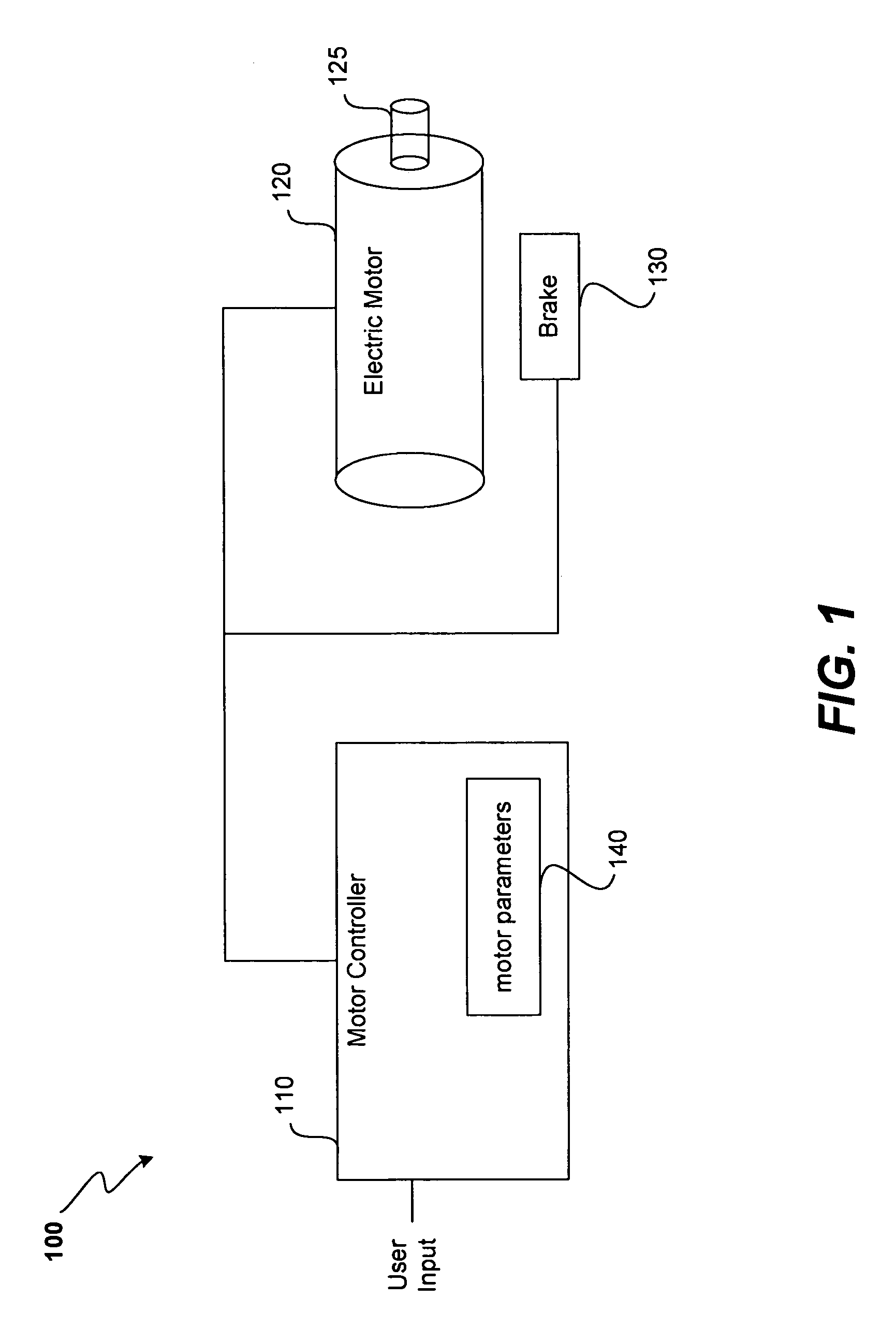
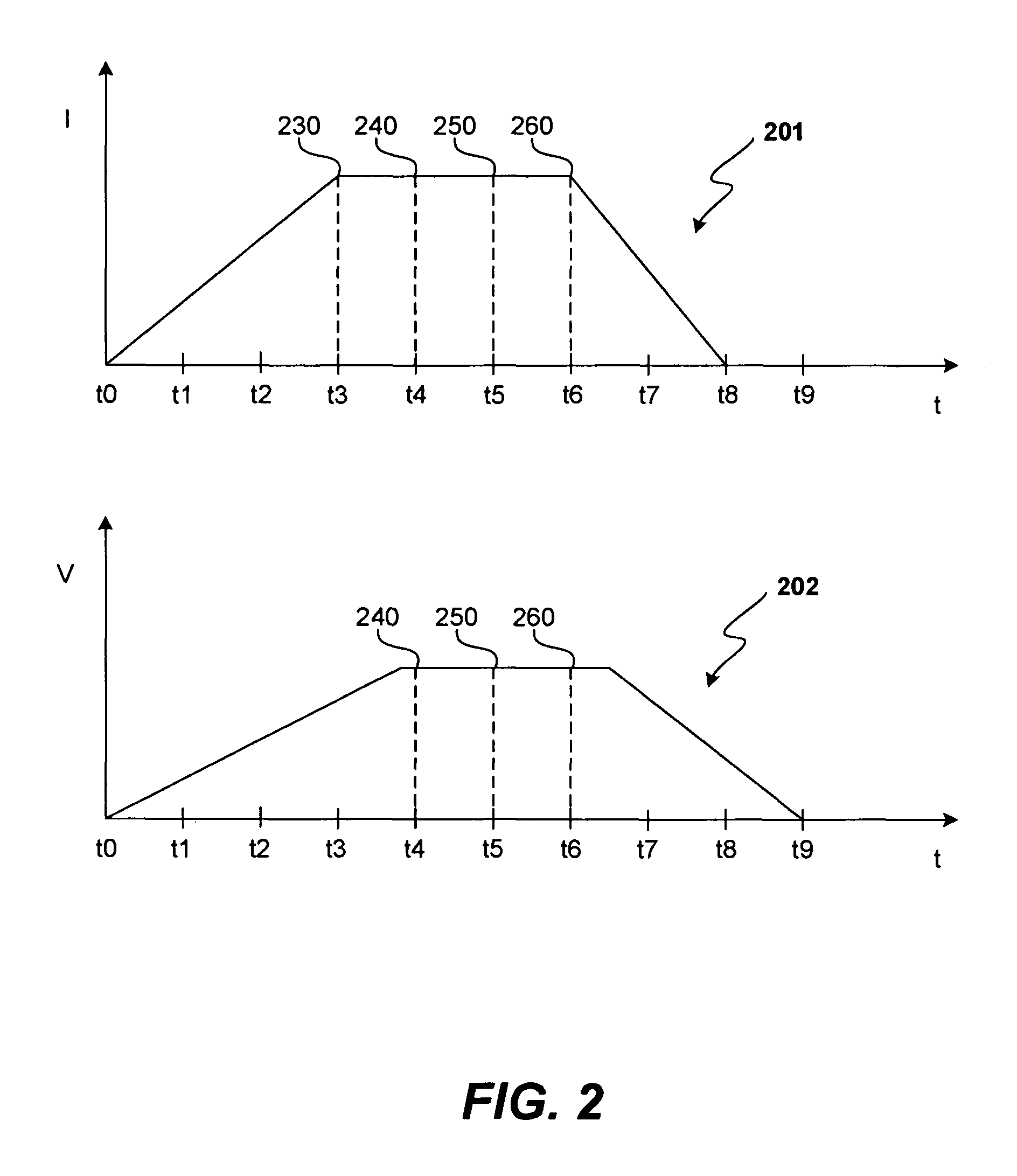

Image

  • Systems and methods for dynamically compensating motor resistance in electric motors
  • Systems and methods for dynamically compensating motor resistance in electric motors
  • Systems and methods for dynamically compensating motor resistance in electric motors

Examples


Embodiment Construction

[0019]In the following description, numerous specific details are set forth in order to provide a thorough understanding of the present invention. It will be apparent, however, to one skilled in the art, that the present invention may be practiced without some or all of these specific details. In other instances, well known process steps have not been described in detail in order not to unnecessarily obscure the present invention.

[0020]The present invention is designed for use in an electric motor controller. As will be described with reference to the following figures, a variety of mechanisms are disclosed for dynamically adjusting a motor resistance parameter stored within an electric motor controller that is used in controlling an electric motor. More particularly, the present invention enables dynamic adjustment of a motor resistance parameter stored within an electric motor controller. The adjustments are based upon measurements taken while operating the motor with the brake en...


PUM


Abstract

Electric motor controllers that dynamically adjust a motor resistance parameter are described. In order to adjust the motor resistance parameter, power is applied the electric motor while the controlled vehicle is stopped and its brake is set so that the vehicle remains stopped while a measurement is taken that can be used to determine motor resistance. A new motor resistance value is then generated based at least in part upon the measurement(s) and the motor resistance parameter is set to the new motor resistance value. The new motor resistance parameter may then be used in the control of the electric motor. In some embodiments, the measurements are taken after the controller receives a brake release request but before actually releasing the brake. The described arrangement can be used in a wide variety of motor controllers and is especially well suited for use in low cost controllers that control motors that are susceptible to wide variations in their resistance such as brushed permanent magnet DC motors.

Description

BACKGROUND OF THE INVENTION[0001]1. Field of the Invention[0002]The present invention relates generally to systems and methods of controlling electric motors. More particularly, the present invention relates to an electronic motor controller that dynamically adjusts a motor resistance parameter used in the control of an electric motor.[0003]2. Description of the Related Art[0004]Electric motors are used in a wide variety of applications. When electric motors are used to drive a vehicle, they are typically controlled by an electric motor speed controller. Generally, a design goal for such motor speed controllers is to control the operational characteristics of the motor so that the motor consistently operates smoothly and safely in a manner that provides a comfortable feel for the operator.[0005]In order to properly control an electric motor, many motor controllers store a set of motor parameters that characterize the electric motor being controlled. The motor controller uses these m...

Claims


Application Information

Patent Timeline
Patent Type & Authority Patents(United States)
IPC IPC(8): G01R31/34
CPCG01R31/343H02P23/14
Inventor DAVIS, MARC R.SHEPHERD, ANDREW J.POST, STEPHEN
Owner CURTIS INSTRUMENTS INC
Learn More