
Radar level gauge system with adaptive transmission power control

a technology of transmission power control and radar level gauge, which is applied in the direction of level indicators by physical variable measurement, engine lubrication, liquid/fluent solid measurement, etc., can solve the problems that conventional radar level gauge systems are generally not well adapted to fulfilling, and achieve low transmission power and high quality of measurement

Inactive Publication Date: 2011-03-01
ROSEMOUNT TANK RADAR
View PDF7 Cites 4 Cited by
  • Summary
  • Abstract
  • Description
  • Claims
  • Application Information

AI Technical Summary

Benefits of technology

The present invention provides an improved radar level gauge system that combines a high quality-of-measurement with low power consumption. The system achieves this by distributing the transmitted power in a way that maximizes the use of the transmitted power while ensuring that the received power level does not exceed a certain level. The system also includes a power sensing circuitry that can discriminate reflected signals from the surface of the product being gauged, and a power level adjusting circuitry that can adjust the transmitted power level based on the received power level. This allows for a sufficient quality-of-measurement while minimizing power consumption. The system can be used in various tank configurations and can be designed to have a small physical extension in relation to the wavelength of the transmitted / received electromagnetic signals.

Problems solved by technology

Conventional radar level gauge systems are generally not well adapted to fulfilling transmission power related regulations while at the same time achieving a high quality-of-measurement level.

Method used


Image

  • Radar level gauge system with adaptive transmission power control
  • Radar level gauge system with adaptive transmission power control
  • Radar level gauge system with adaptive transmission power control

Examples


Embodiment Construction

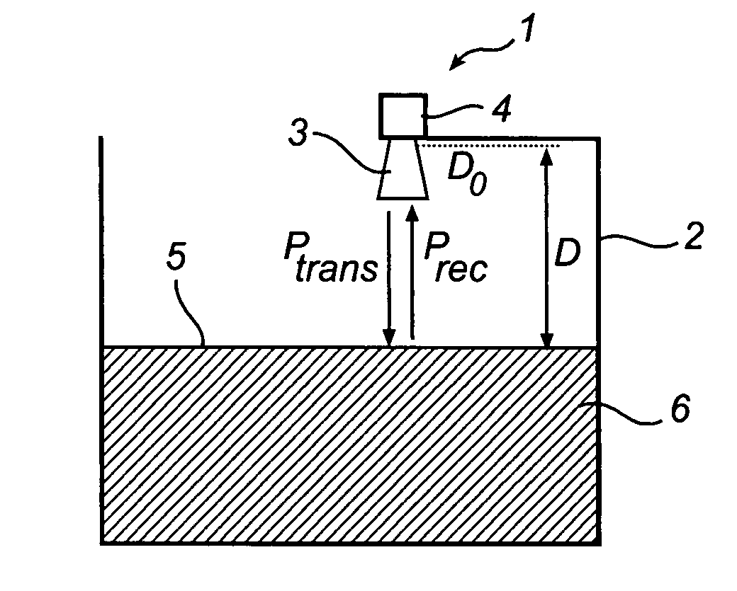
[0033]In the present description, embodiments of the present invention are mainly described with reference to a radar level gauge system having a horn antenna and being mounted on an open tank containing a product. It should be noted that this by no means limits the scope of the invention, which is equally applicable to radar level gauge systems implemented in other applications, open, semi-open as well as closed, such as for level determination in open tanks, floating roof tanks, reservoirs, rivers and other watercourses, etc.

[0034]Moreover, the radar level gauge system according to the present invention may be equipped with any other type of antenna, such as a patch antenna, a rod antenna or an array antenna.

[0035]In FIG. 1, a radar level gauge system 1 according to an embodiment of the present invention is schematically shown mounted on an open tank 2. The radar level gauge system 1 has a propagating device, here in the form of a horn antenna 3, and a control unit 4 including (al...


PUM


Abstract

A radar level gauge system, for determining a filling level of a product contained in a tank, the radar level gauge system comprising a transceiver including a signal generator for generating electromagnetic signals for transmission; a transmitter branch for transmitting the electromagnetic signals; and a receiver branch for receiving electromagnetic signals. The radar level gauge system further comprises a propagation device for allowing transmitted electromagnetic signals to propagate towards a surface of the product inside the tank, where signals are reflected, and for returning reflected electromagnetic signals back from the surface of the product; processing circuitry connected to the transceiver and configured to determine the filling level based on the reflected electromagnetic signals; power sensing circuitry connected to the transceiver and configured to determine a received power level of received electromagnetic signals; and power level adjusting circuitry provided on the transmitter branch of the transceiver, connected to the power determination circuitry, and configured to adjust a transmitted power level of the transmitted electromagnetic signals in response to the determined received power level of the reflected electromagnetic signals.

Description

[0001]The present application is claims priority of Sweden patent application Serial No. 0701228-9, filed May 16, 2007, the content of which is hereby incorporated by reference in its entirety.TECHNICAL FIELD OF THE INVENTION[0002]The present invention relates to a radar level gauge system, for determining a filling level of a product.TECHNICAL BACKGROUND[0003]Radar level gauge systems are today in use in a variety of fields of application for accurate level determination, as well as for determination of other product parameters, such as temperature, flow etc. For determining the level of a product by means of a radar level gauge system, electromagnetic signals are transmitted and propagated, usually by means of an antenna, towards a surface of the product, where signals are reflected. The reflected signals are received by the radar level gauge system, and the distance between a reference position and the surface of the product is determined by comparing the transmitted signals with...

Claims


Application Information

Patent Timeline
Patent Type & Authority Patents(United States)
IPC IPC(8): G01F23/28
CPCG01F23/284
Inventor JIRSKOG, ANDERS
Owner ROSEMOUNT TANK RADAR
Learn More