Print control with interfaces provided in correspondence with printing methods
a printing method and interface technology, applied in the field of printing control methods, can solve the problems of difficulty in memorizing all the various combinations of printers, unsuitable approach to permit the full range of functions/abilities of each printer to be sufficiently utilized, etc., and achieve the effect of convenient printing setting
- Summary
- Abstract
- Description
- Claims
- Application Information
AI Technical Summary
Benefits of technology
Problems solved by technology
Method used
Image
Examples
first embodiment
[0039]A preferred embodiment to which the invention is applied will be described hereinbelow.
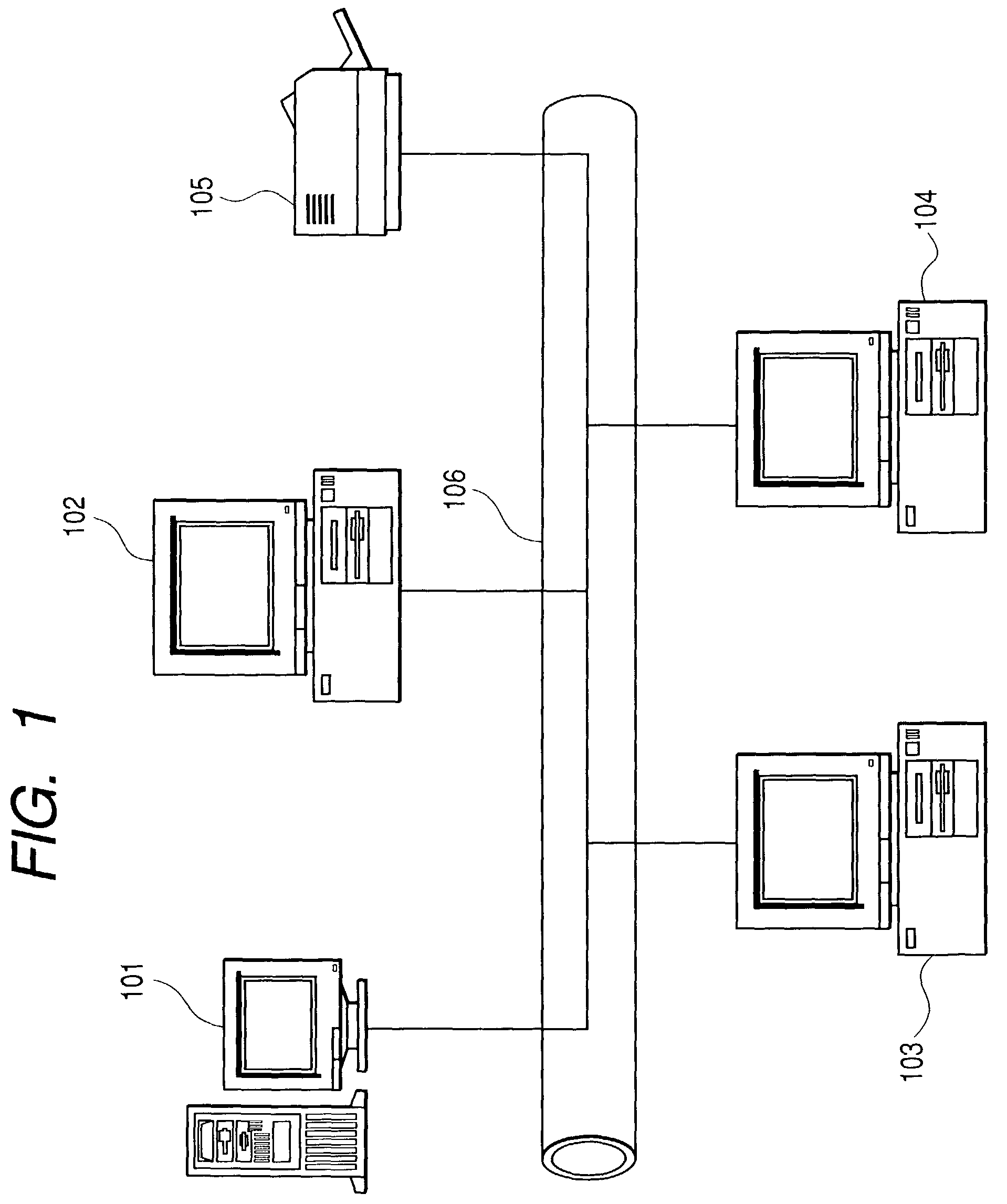
[0040]FIG. 1 is a block diagram for explaining the construction of an information processing system to which the invention can be applied. It is presumed that in the present system, one or a plurality of client computers are connected.
[0041]In FIG. 1, reference numerals 102, 103, and 104 denote information processing apparatuses serving as client computers (clients). These client computers are connected to a network 106 by a network cable such as Ethernet (registered trademark) or the like and can execute various programs such as an application program and the like. A printer driver having a function for converting print data into a printer language corresponding to a printer has been installed in each information processing apparatus. It is assumed that the printer driver supports a plurality of printer drivers.
[0042]Reference numeral 101 denotes an information processing apparatus serving ...
second embodiment
[0189]In the second embodiment, an explanation will be made with respect to an example in the case where the color / black and white distribution has been selected and set as an outputting method in step S1701 in FIG. 17 in the first embodiment.
[0190]In the second embodiment, a fundamental flow of processes is substantially the same as that of the first embodiment, except that the UIs which are displayed in steps S1702 and S1703 in FIG. 17 and the setting of the member printer drivers as conflict targets which are set in S1704 are merely different from those in the first embodiment, and other aspects of the construction are the same. Therefore, it is assumed that only portions which are peculiar to those examples are extracted and explained.
[0191]FIG. 21 is a diagram showing an example of a display state of the UI of the group printer driver at the time when the color / black and white distribution has been designated as an outputting method in step S1701 in FIG. 17.
[0192]The color / blac...
third embodiment
[0197]In the third embodiment, an explanation will be made with respect to an example in the case where the multiple address has been selected and set as an outputting method in step S1701 in FIG. 17 in the first embodiment.
[0198]In the third embodiment, the fundamental flow of processes is substantially the same as that of the first embodiment, except that the UIs which are displayed in steps S1702 and S1703 in FIG. 17 and the setting of the member printer drivers as conflict targets which are set in S1704 are different from those in the first embodiment, and other aspects of the construction are the same. Therefore, the points of difference will be explained particularly in detail.
[0199]FIG. 22 is a diagram showing an example of a display state of the UI in the case where the multiple address print has been selected and set as an outputting method via the predetermined pointing device such as a mouse or the like.
[0200]The multiple address print indicates a print outputting method ...
PUM
 Abstract
Description
Claims
Application Information
 - R&D
- Intellectual Property
- Life Sciences
- Materials
- Tech Scout
- Unparalleled Data Quality
- Higher Quality Content
- 60% Fewer Hallucinations
Browse by: Latest US Patents, China's latest patents, Technical Efficacy Thesaurus, Application Domain, Technology Topic, Popular Technical Reports.
© 2025 PatSnap. All rights reserved.Legal|Privacy policy|Modern Slavery Act Transparency Statement|Sitemap|About US| Contact US: help@patsnap.com


