Method and apparatus for active power factor correction without sensing the line voltage

a technology of active power factor and line voltage, which is applied in the direction of electrical energy, process and machine control, instruments, etc., can solve the problems of poor multiplier operation, low efficiency, and inability to detect noise and distortion in the rectified ac voltage, so as to reduce the power consumption when the load is ligh

Inactive Publication Date: 2011-02-22
BEELAB SEMICON
View PDF3 Cites 8 Cited by
  • Summary
  • Abstract
  • Description
  • Claims
  • Application Information

AI Technical Summary

Benefits of technology

[0019]An advantage of the present invention is the use of simple integrators only such that theoretical unity power factor can be achieved. Another advantage of the present invention is that the conducted EMI is improved over the prior arts. Another advantage of the present invention is the switching loss of the AC / DC converter under controlled falls with the loading because the switching frequency decreases under light loading. Another advantage of the present invention is the switching frequency falls with the loading of the converter such that the no extra circuitry is needed to reduce the power consumption when the loading is light.
[0020]Thus the present invention has a number of improvements over the prior arts.
[0021]These and other objects and advantages of the present invention will become clear to those skilled in the art in view of the description of the best presently known mode of carrying out the invention and the industrial applicability of the preferred embodiment as described herein and as illustrated in the several figures of the drawings.

Problems solved by technology

This category suffers from the problem of feedback loop stability when the AC line voltage varies over a wide range, e.g. from 115 AV to 240 VAC.
They use complicated compensation network to ensure stability and is susceptible to noise and distortion in the rectified AC voltage.
However, it is hard to have a good multiplier which can operate at large input signal and this problem bounds the best achievable power factor.
However, they are applicable to limited type of converters only.
Both categories use Pulse Width Modulation (PWM) to control the switch inside the AC / DC converter and suffer from the problem of concentrated EMI.
Thus the complexity of the design becomes double.
This implies extra circuitry and more complex control to ensure the controllers transit smoothly between the light loading mode and normal loading mode.
However, conventional AC / DC converters which do not has a Power Factor Correction front stage will suffer from the problem of larger output ripple at medium load.

Method used


Image

  • Method and apparatus for active power factor correction without sensing the line voltage
  • Method and apparatus for active power factor correction without sensing the line voltage
  • Method and apparatus for active power factor correction without sensing the line voltage

Examples


Embodiment Construction

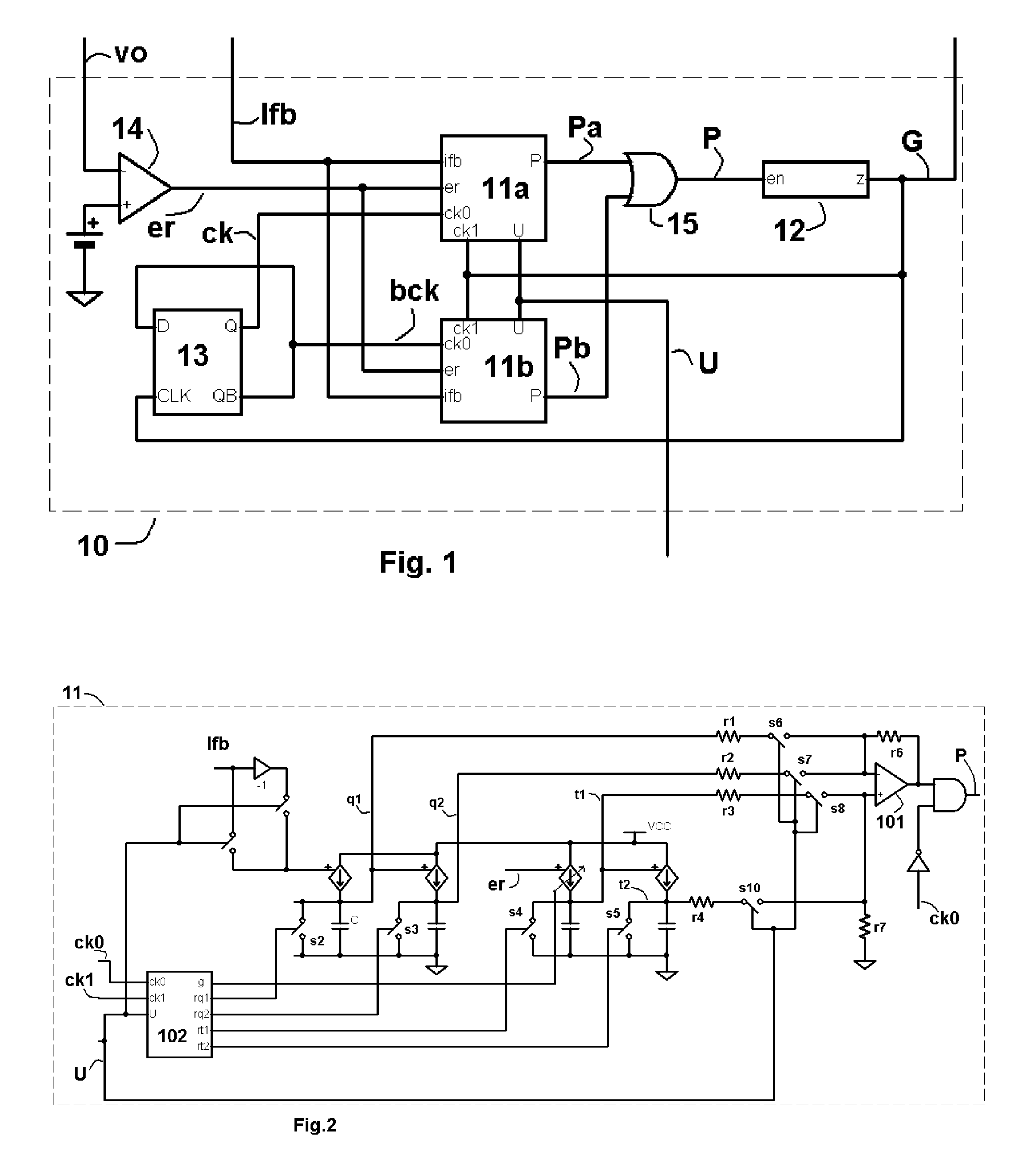
[0039]The prior art U.S. Pat. No. 5,867,379 set forth a means to provide power factor correction without sensing the line voltage. The basic assumption behind U.S. Pat. No. 5,867,379 is that the pulse on time is unknown but the switching period is fixed. To maintain the causality of the derived equation, the same approach can only be applied to limited type of switching converters. However, by allowing the pulse on time be fixed and the pulse off time be an unknown, the causality of the derived equation can be assured in all kinds of converters. Thus Pulse Frequency Modulation (PFM) instead of PWM is used. The immediate advantage is that the resulting equations are linear and are well suitable for implementation in hardware using simple integrators. This PFM approach is the basis of the present invention.

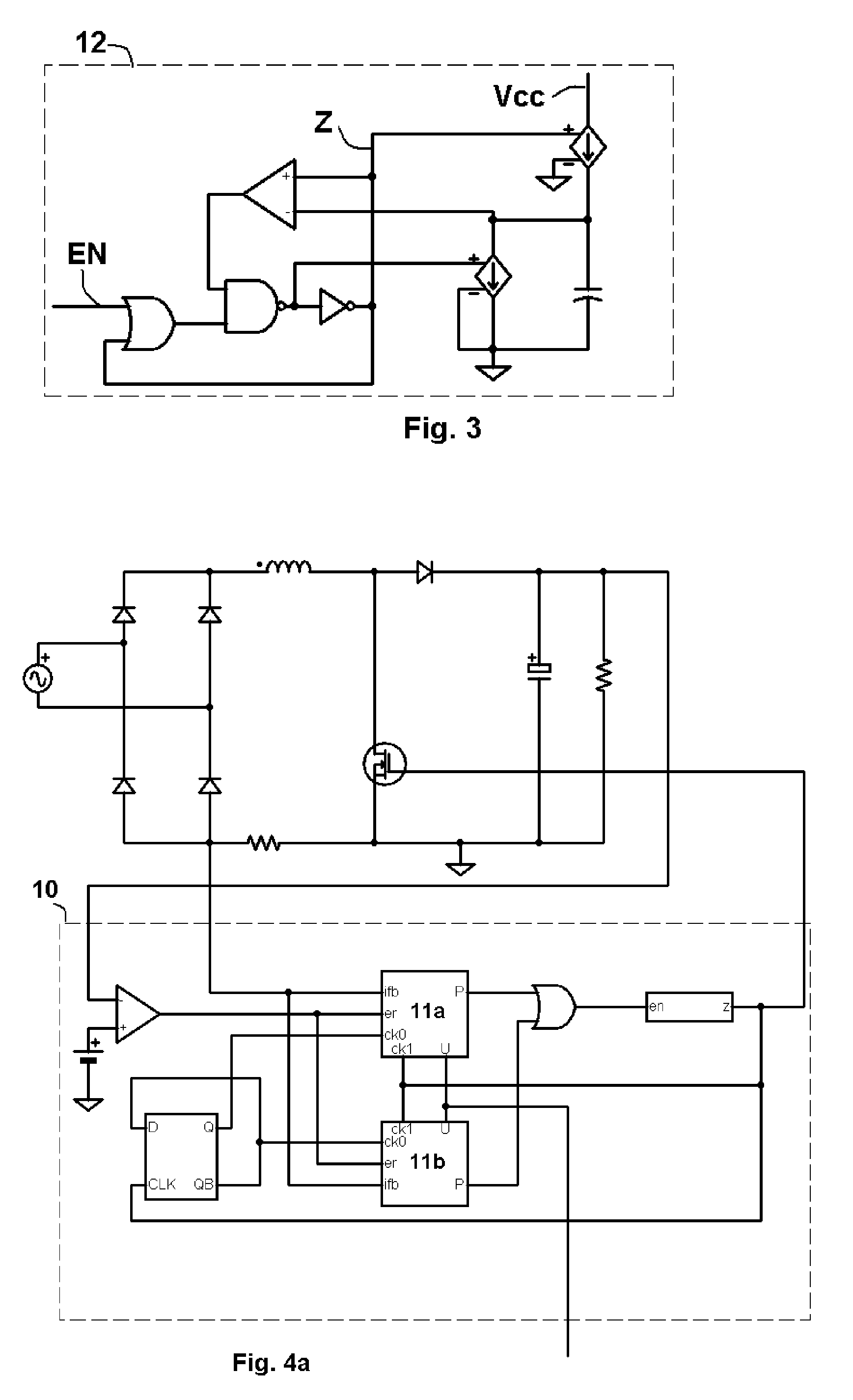
[0040]For a boost converter working in the continuous mode, the inductor current IL, the output voltage Vo, the target output voltage Vr, the rectified line voltage Vg, the switch o...


PUM


Abstract

A power factor correction apparatus which uses Pulse Frequency Modulation (PFM) to control an AC / DC converter is disclosed. Only a current signal from the converter is used to determine the switching frequency. Sensing of the input line voltage is not needed. The switching frequency varies with the line voltage such that the converter emulates a resistive load. By using PFM control, EMI is spread over a range rather than concentrated at a few frequencies. Thus a smaller EMI filter can be used. Since the switching frequency decreases with the loading of the converter, the switching loss decreases with the loading as well. Thus, the need of meeting efficiency standards, e.g. the 80 PLUS and Energy Star, can be fulfill without extra circuitry.

Description

FIELD OF INVENTION[0001]The present invention relates to the field of switching mode power supplies. More particularly, the present invention relates to a method and apparatus which controls the operation of a AC / DC converter using Pulse Frequency Modulation to achieve high power factor and low standby power at light loading without sensing the line voltage.BACKGROUND OF INVENTION[0002]There is a need for all power supplies connected to the mains to meet the harmonic limits of the European standard EN-61000-3-2 or similar in other countries. There are further needs to meet efficiency standards, e.g. 80 PLUS and Energy Star, in future. Prior arts which can meet the EN-61000-3-2 requirements can be divided into two categories.[0003]The first category (U.S. Pat. No. 4,437,146, U.S. Pat. No. 5,134,355, U.S. Pat. No. 5,654,880, U.S. Pat. No. 6,900,623, US2006 / 0158912) senses the rectified AC voltage and controls the operation of the converter using a feedback loop such that the line inpu...

Claims


Application Information

Patent Timeline
Patent Type & Authority Patents(United States)
IPC IPC(8): G05F1/70
CPCG05F1/70H02M1/4225Y02P80/112Y02B70/126Y02B70/10Y02P80/10
Inventor NG, SHEKWAI
Owner BEELAB SEMICON
Why Eureka
Try Eureka