
Battery security device

a security device and battery technology, applied in the field of battery security devices, can solve the problems of increasing production and cost steps, difficult to cover b>3/b>a, and avoiding power failure, so as to increase the pressure stroke of the elastic arm, avoid power failure, and avoid the effect of increasing the strength of the devi

Inactive Publication Date: 2011-02-22
ALTEK CORP
View PDF8 Cites 2 Cited by
  • Summary
  • Abstract
  • Description
  • Claims
  • Application Information

AI Technical Summary

Benefits of technology

[0008]The primary object of the invention is therefore to specify a battery security device can increase a pressure stroke of an elastic arm, to avoid power failure caused of the shake of the battery. In addition, the strength to cover the device will not increase, and no additional elements will be applied for easy usage and low cost.
[0009]According to the invention, the object is achieved to provide a battery security device includes a holder, a cover and at least one flexible plate. The holder contains the battery. The cover slips to set on the holder and has at least one raised lump to press the flexible plate. The flexible plate is set between the holder and the cover and has at least one elastic arm. The elastic arm has a stressed portion and at least one contact portion. When the cover slips to set on the holder, the raised lump presses down the stressed portion to increase the pressure of the elastic arm for avoiding power failure caused of the battery be shook. Further the device to fix a battery does not increase the force of setting the cover and not need any other component. To sum up, the device to fix a battery of present invention has low cost and friendly use.

Problems solved by technology

When the length of the battery is short, the resilient contacts suddenly come off the battery due to shakes causes power failure.
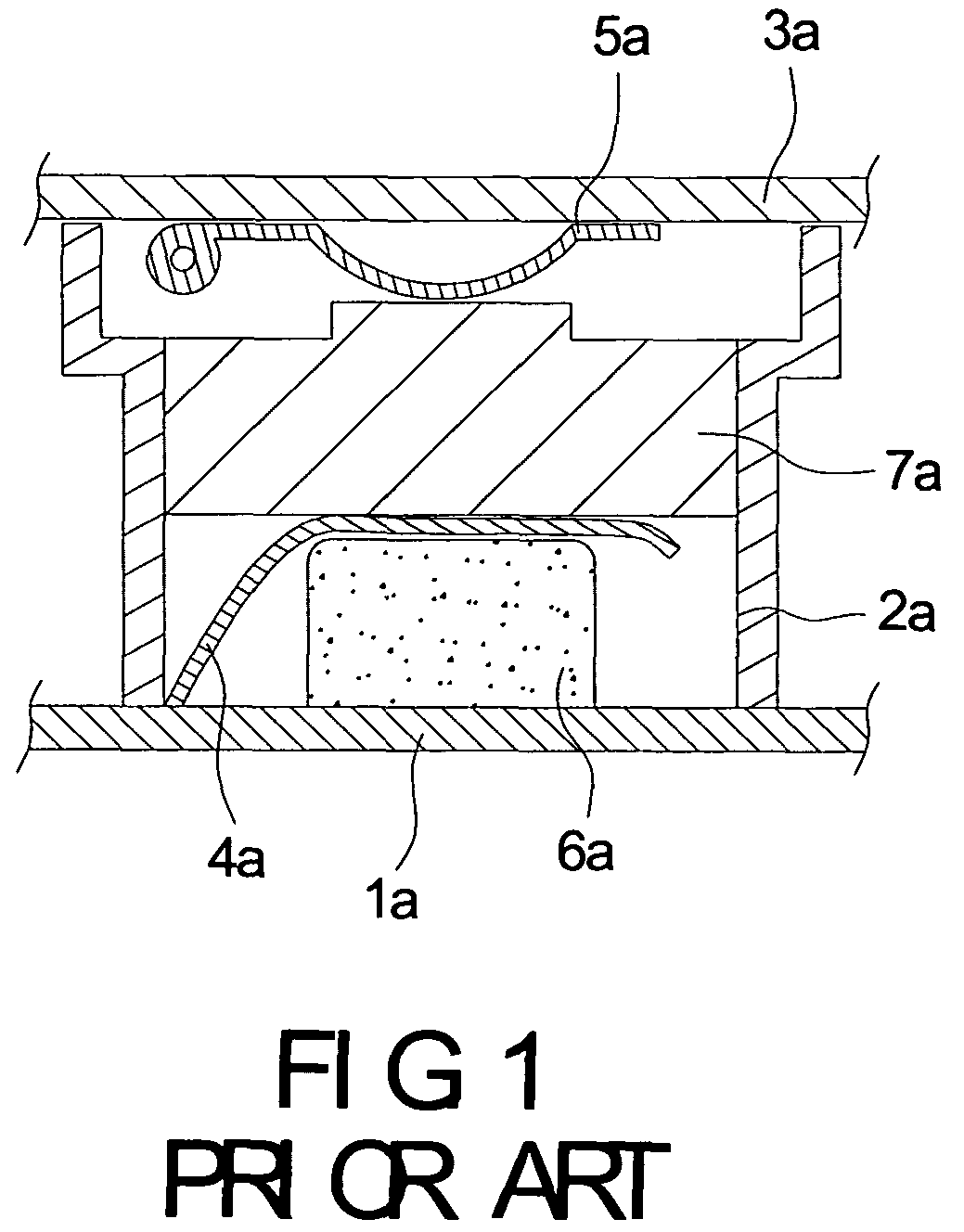
However, the cover 3a is difficult to cover because of the location of the sponge 6a.
And the arrangement of the sponge 6a increases steps of production and cost.

Method used


Image

  • Battery security device
  • Battery security device
  • Battery security device

Examples


Embodiment Construction

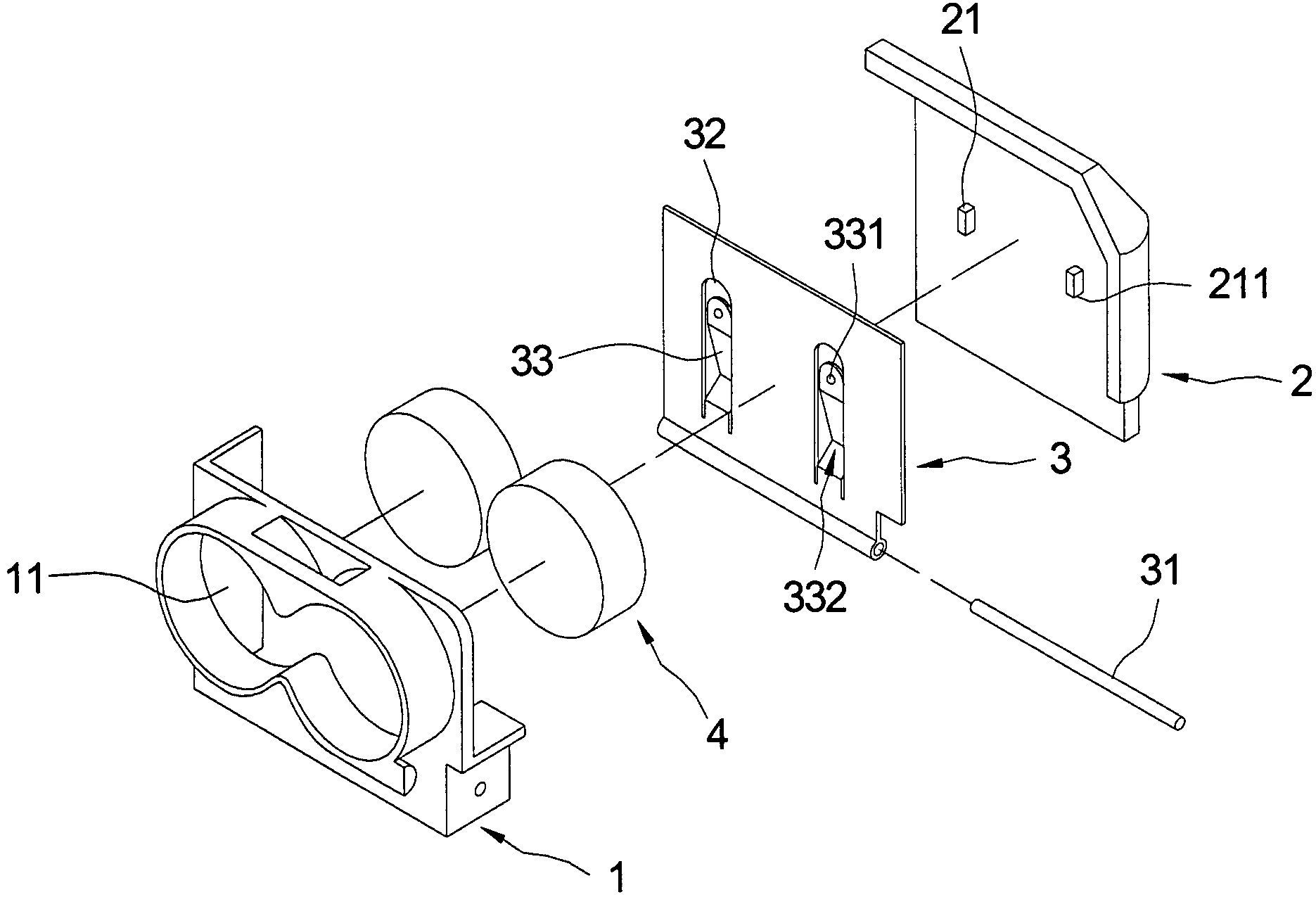
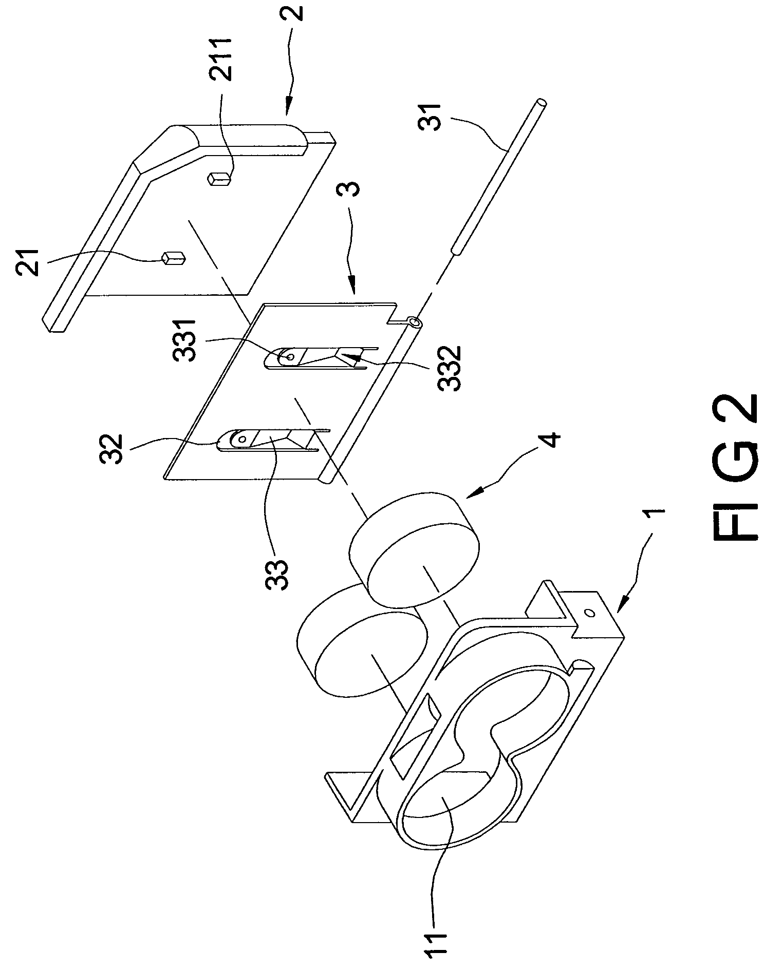
[0016]Referring in FIGS. 2, 3A and 3B, a battery security device according to the present invention includes a holder 1, a cover 2 and at least one flexible plate 3.

[0017]The holder 1 is made of insulation materials. The holder 1 has a containing cavity 11 and two slots communicated with two opposite ends of the containing cavity 11. The holder 1 is connected to a battery base (not shown) via a bottom thereof. Inside the containing cavity 11, there are two batteries 4, which electrically connect to the battery base via electrodes (not shown) thereof.

[0018]The cover 2 is slipped on the holder 1 and has two raised lumps 21, which are rectangular. The two raised lumps 21 and the cover 2 are made integrally in one piece. Each of the raised lumps 21 includes a push portion 211 arranged at a bottom thereof and being slant. The cover 2 retains against the flexible plate 3 via the push portion 211s of the raised lumps 21. In addition, the raised lump 21 can be rectangular, square, elliptica...


PUM

PropertyMeasurementUnit
flexibleaaaaaaaaaa
forceaaaaaaaaaa
elasticaaaaaaaaaa

Abstract

A battery security device includes a holder, a cover and at least one flexible plate. The holder contains the battery. The cover slips to set on the holder and has at least one raised lump to press the flexible plate. The flexible plate is set between the holder and the cover and has at least one elastic arm. The elastic arm has a stressed portion and at least one contact portion. When the cover slips to set on the holder, the raised lump presses down the stressed portion to increase the pressure of the elastic arm for avoiding power failure caused of the battery be shook. Further the device to fix a battery does not increase the force of setting the cover and not need any other component. To sum up, the device to fix a battery of present invention has low cost and friendly use.

Description

BACKGROUND OF THE INVENTION[0001]1. Field of the Invention[0002]The present invention relates to a battery security device, and particularly relates to a battery security device for avoiding power failure caused of the battery is shook.[0003]2. Background of the Invention[0004]A conventional device to fix the battery provides electrical connection via resilient contacts touching two opposite ends of the battery. Due to the different length of each battery, the pressure stroke between the battery and the resilient contacts will vary thereby. When the length of the battery is short, the resilient contacts suddenly come off the battery due to shakes causes power failure.[0005]To avoid power failure mentioned above, an additional sponge is applied in the battery base in order to increase the pressure stroke for touching the resilient contact. Referring to FIG. 1, a conventional battery device includes a battery base 1a, a holder 2a, a cover 3a, a lower resilient contact 4a, an upper res...

Claims


Application Information

Patent Timeline
Patent Type & Authority Patents(United States)
IPC IPC(8): H01M2/10
CPCH01M10/42H01M2/105H01M50/213Y02E60/10
Inventor HUANG, YU-CHENGLIN, TZU-CHIH
Owner ALTEK CORP
Learn More