
Remote fire extinguisher station inspection

a fire extinguisher and remote inspection technology, applied in the direction of fluid tightness measurement, instrumentation, container discharging methods, etc., can solve the problems of inability to address the number of missing or non-functioning fire extinguishers, and the cost of more frequent inspection procedures

Inactive Publication Date: 2011-02-22
ENGAUGE
View PDF137 Cites 31 Cited by
  • Summary
  • Abstract
  • Description
  • Claims
  • Application Information

AI Technical Summary

Benefits of technology

Preferred embodiments of this aspect of the invention may include one or more of the following additional features. The electronic circuit comprises at least one detector for the at least one predetermined internal condition, the at least one detector for the at least one predetermined internal condition being adapted to initiate a signal to the remote central station upon detection of the at least one predetermined internal condition. Preferably, the at least one detector for the at least one predetermined internal condition comprises the fire extinguisher gauge for detecting the out-of-range pressure condition of fire extinguishing material contained within the volume of the fire extinguisher tank at the fire extinguisher station. More preferably, the fire extinguisher gauge comprises a gauge pointer and a gauge scale, the gauge pointer being moveable relative to the gauge scale for indication of pressure, and the apparatus further comprises a magnet mounted to the gauge pointer and at least one sensor, e.g., a Hall Effect sensor responsive to proximity of the magnet as the tank approaches an out-of-range pressure condition. Preferably, the out-of-range pressure condition comprises a low-pressure condition and/or a high-pressure condition, and the at least one sensor comprises at least one Hall Effect sensor positioned to detect the low-pressure condition and/or at least one Hall Effect sensor positioned to detect the high-pressure condition. The Hall Effect sensor is mounted generally in a plane of the gauge scale, e.g., at a rear surface of the gauge scale. The electronic circuit comprises at least one detector for the at least one predetermined external condition, the detector being adapted to initiate a signal to the remote central station upon detection of the at least one predetermined external condition. Preferably, the at least one predetermined external condition comprises movement and/or removal of the fire extinguisher relative to its installed position at the fire extinguisher station. The at least one predetermined external condition comprises presence of an obstruction to viewing of or access to the fire extinguisher station. The obstruction is disposed within a range of about 6 inches to about 10 feet from the fire extinguisher station. The at least one detector for the at least one predetermined external condition comprises a proximity sensor, e.g., comprising a sound wave emitter and a sound wave detector. Preferably, the proximity sensor comprises an ultrasonic transducer. The docking station comprises at least one detector for the at least one predetermined external condition comprising an electronic tether engaged and in electronic communication between the docking station and the fire extinguisher, and movement of the fire extinguisher relative to its installed position at the fire extinguisher station dislodges engagement of the tether and severs electronic communication, to initiate a signal to the remote central station indicative of the at least one predetermined external condition comprising lack of presence of the fire extinguisher in its installed position at the fire extinguisher station. Preferably, movement of the fire extinguisher relative to its installed position at the fire extinguisher station to dislodge engagement of the

Problems solved by technology

Procedures for more frequent inspections are generally considered cost prohibitive, even where it is recognized that a problem of numbers of missing or non-functioning fire extinguishers may not be addressed for days or even weeks at a time, even where manpower may otherwise be available.

Method used


Image

  • Remote fire extinguisher station inspection
  • Remote fire extinguisher station inspection
  • Remote fire extinguisher station inspection

Examples


Embodiment Construction

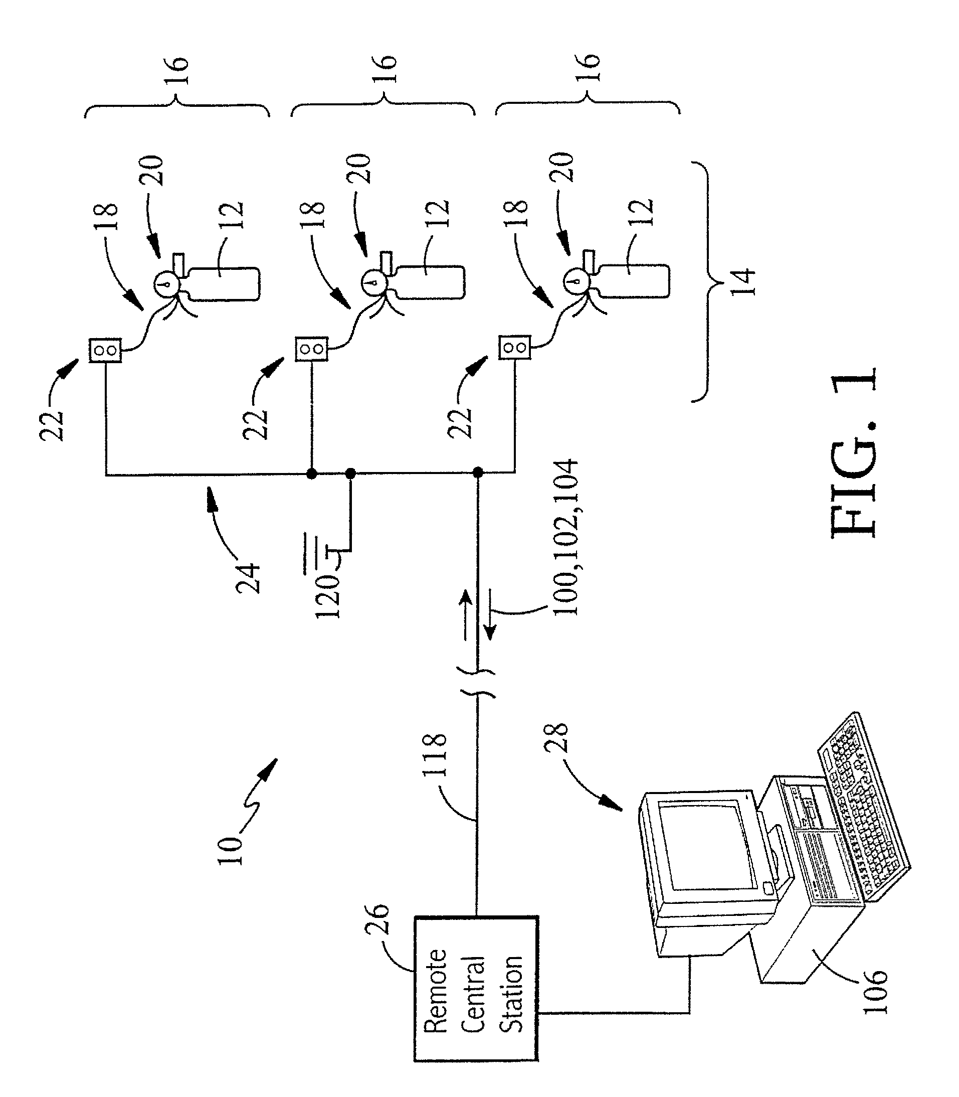
Referring to FIG. 1, an apparatus 10 of the invention for remote inspection of portable fire extinguishers 12 installed at one or a system 14 of fire extinguisher stations 16 includes means 18 for detecting lack of presence of a fire extinguisher 12 in its installed position at a fire extinguisher station 16, means 20 for detecting out-of-range pressure of the contents of a fire extinguisher 12 at a fire extinguisher station 16, means 22 for detecting an obstruction to viewing of or access to a fire extinguisher station 16, and means 24 for transmission of inspection report information for each of the fire extinguisher stations 16 to a remote central station 26. The apparatus 10 further includes means 28 for maintaining a record of inspection report information.

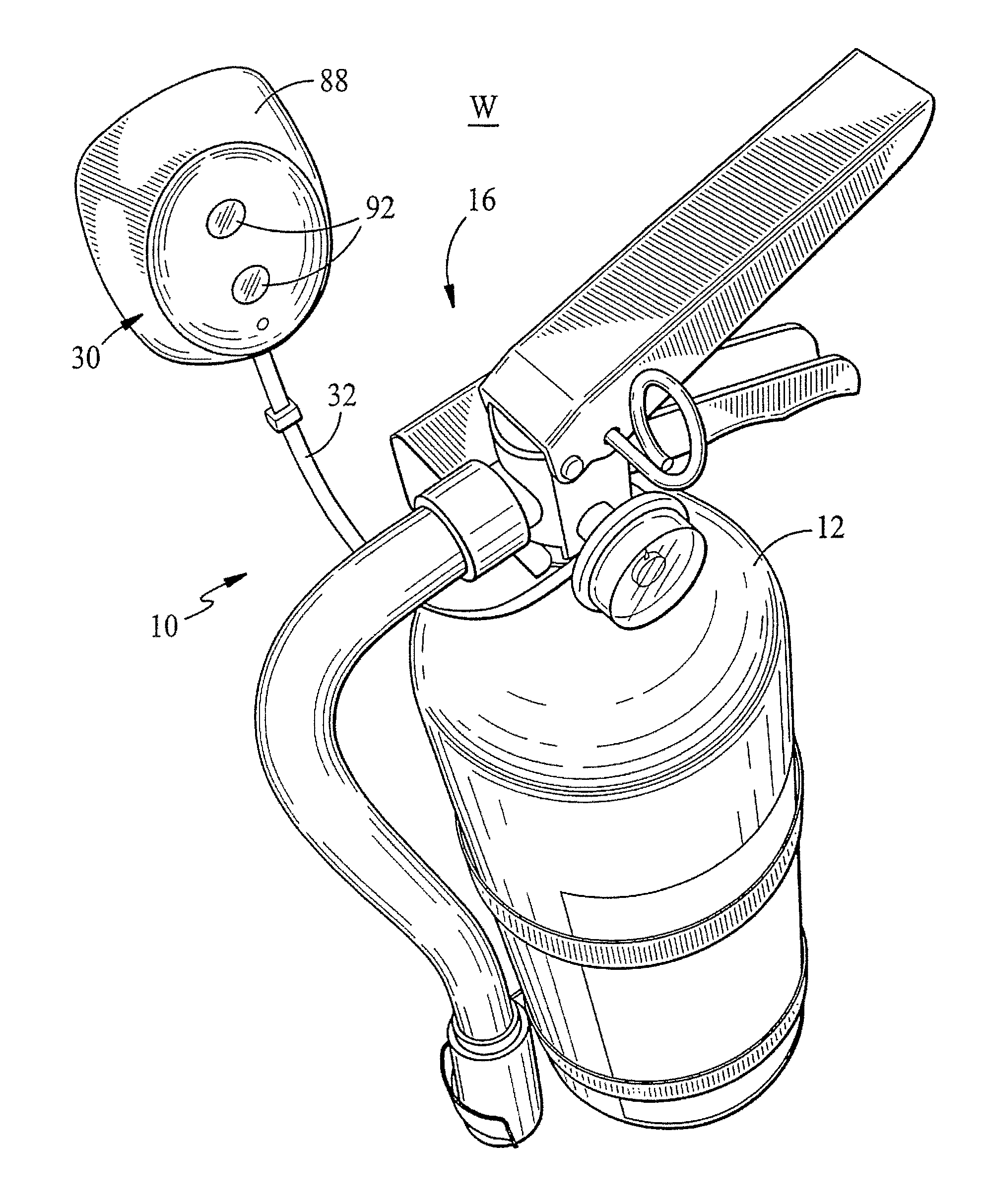
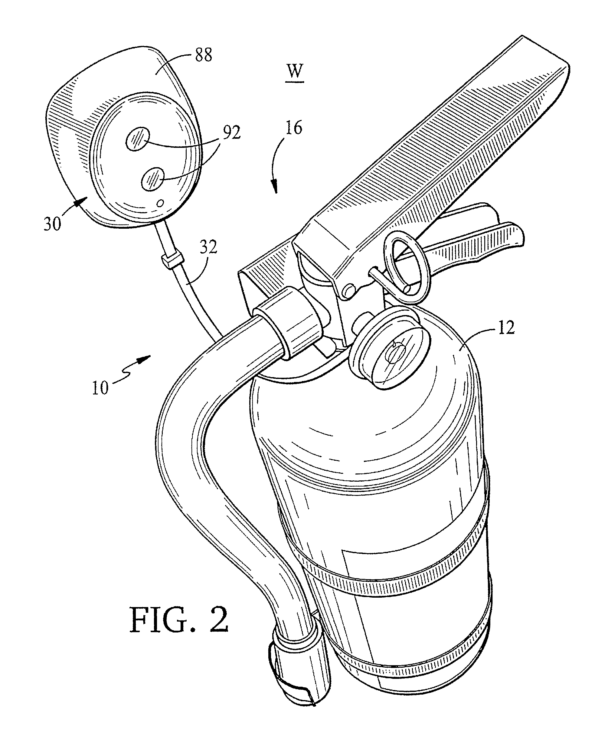
As an example of a remote inspection apparatus 10 of the invention, in FIG. 2, a portable fire extinguisher 12 is shown mounted to a wall, post, or other support surface, W, at a fire extinguisher station 16 in a system of fi...


PUM


Abstract

An apparatus for remote inspection of fire extinguishers at one or a system of fire extinguisher stations includes, e.g., at each fire extinguisher station: a detector for lack of presence of a fire extinguisher in its installed position at the fire extinguisher station; a detector for out-of-range pressure of contents of the fire extinguisher at the fire extinguisher station; a detector for an obstruction to viewing of or access to the fire extinguisher at the fire extinguisher station; and a device for transmission of inspection report information from the fire extinguisher station to a remote central station.

Description

BACKGROUNDPortable fire extinguishers are stationed for use in case of a fire in all manner of environments. Typically, the fire extinguishers are placed in standby condition at a system of fire extinguisher stations found throughout a facility at locations selected for reasonably easy access in a fire emergency. Standards and procedures for periodic inspection of fire extinguishers at fire extinguisher stations are set forth by the National Fire Protection Association (NFPA) in “NFPA 10 Standard for Portable Fire Extinguishers” (1998 Edition), the complete disclosure of which is incorporated herein by reference. In its relevant portion (§4-3.2), NFPA 10 sets forth the elements of the inspection of fire extinguishers and fire extinguisher stations required to take place at regular intervals, e.g., approximately every thirty days, as follows:4-3.2 Procedures Periodic inspection of fire extinguishers shall include a check of at least the following items:(a) Location in designated plac...

Claims


Application Information

Patent Timeline
IPC IPC(8): G01F23/00A62C13/76G01F23/60G01F23/62
CPCA62C37/50F17C13/084G01F23/0076G01F23/62F17C2201/0109F17C2201/0119F17C2201/032F17C2201/058F17C2203/0624F17C2205/0111F17C2205/0126F17C2205/0165F17C2205/0188F17C2205/0329F17C2205/052F17C2221/03F17C2223/0123F17C2223/035F17C2250/032F17C2250/034F17C2250/036F17C2250/043F17C2250/0478F17C2250/072F17C2260/015F17C2265/04F17C2270/0754G01F23/804
Inventor MCSHEFFREY, JOHN J.MCSHEFFREY, BRENDAN T.
Owner ENGAUGE
Learn More