
Optical transmission apparatus

a technology of optical transmission apparatus and pluggable optical modules, which is applied in the field of optical transmission apparatuses, can solve the problems of not having universal applicability, inability to allow a client to use, and inability to adapt to the apparatus, so as to widen the range of pluggable optical modules and facilitate maintenance.

Inactive Publication Date: 2011-02-15
FUJITSU LTD
View PDF8 Cites 4 Cited by
  • Summary
  • Abstract
  • Description
  • Claims
  • Application Information

AI Technical Summary

Benefits of technology

[0021]According to at least one embodiment of the present invention, the optical transmission apparatus can clearly define the range of product guarantee while providing ease of maintenance and cost advantage, and can widen the range of choices of pluggable optical modules to be used.

Problems solved by technology

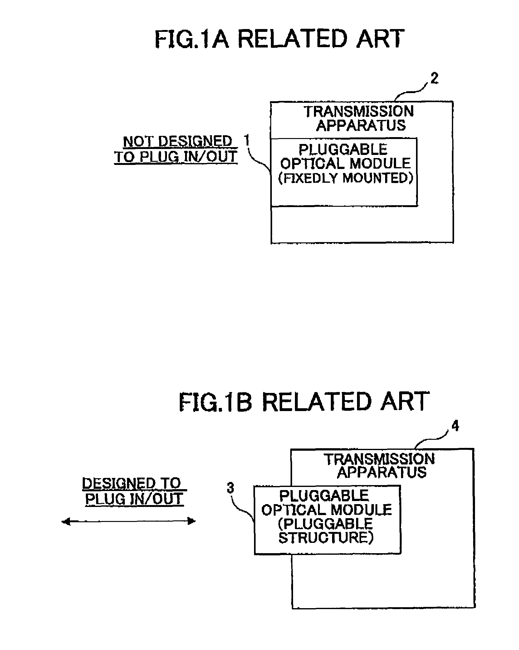
Optical transceivers (optical modules) used in optical transmission apparatuses provided for backbone networks as typified by SONET, SDH, WDM, etc., are developed by makers and manufacturers using their own designs and interfaces, and thus do not possess universal applicability.
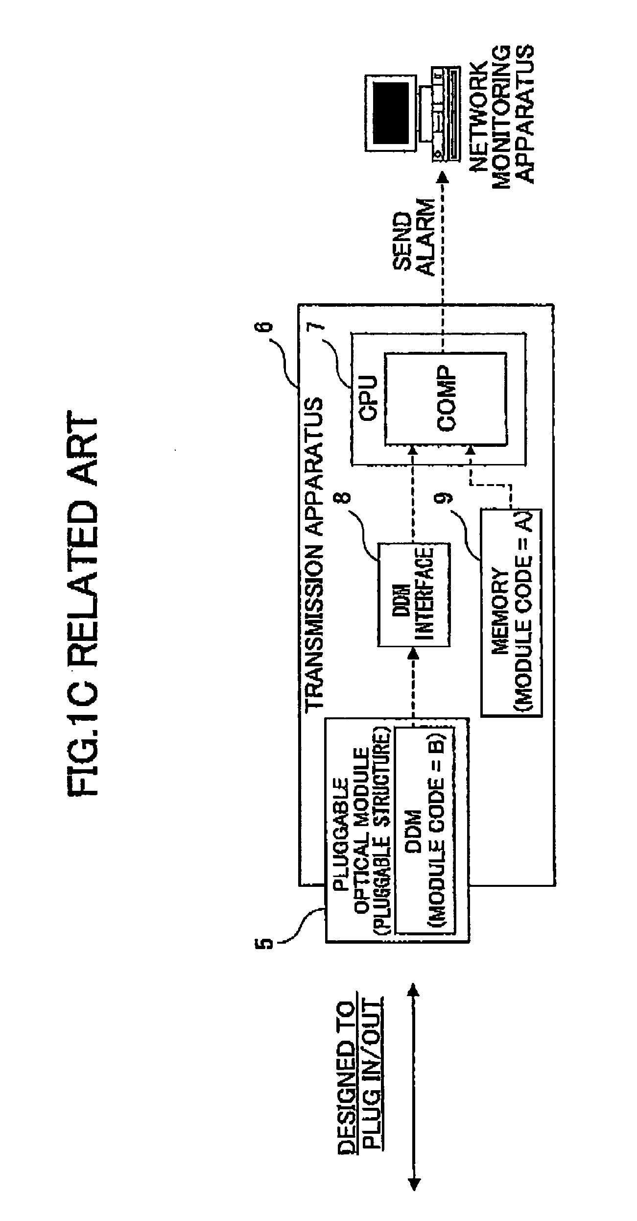
When pluggable optical modules are employed for optical transmission modules, the main issue is how to keep balance between the reliability of the apparatuses and the convenience of the pluggable optical modules (high availability, easy maintenance, low cost, and so on).
The first usage type cannot make use of the convenience of a pluggable optical module such as the fact that it is pluggable, and, also, cannot allow a client to use an optical module that the client obtained through his / her own channel.
The second usage type raises concern that a pluggable optical module not suitable to the apparatus or a poor-quality module may be used.
In the worst case, there is a possibility of having a situation in which the communication channel fails while it is used.
That is, the reliability of the apparatus may not be guaranteed.
Further, it is not possible for a client (communication carrier) using the apparatus to make its own choice to select an inexpensive pluggable optical module.
Further, if an inexpensive pluggable optical module that is not fully supported by the manufacture is chosen, there is a need to check, before putting this pluggable optical module into operation, whether this module properly operates in the optical transmission apparatus and whether this module has sufficient characteristics for operation of the communication channel.
In reality, however, the conditions of use, transmission distance, etc., differ from communication line to communication line, and not all the optical modules are used in the worst conditions.
Against this background, the reduction of a number of process steps for product certification is an important issue.

Method used


Image

  • Optical transmission apparatus
  • Optical transmission apparatus
  • Optical transmission apparatus

Examples


Embodiment Construction

[0029]In the following, embodiments of the present invention will be described with reference to the accompanying drawings.

[0030]

[0031]FIG. 2 is a drawing showing the configuration of an embodiment of a network system that is constructed by use of an optical transmission apparatus of the present invention. In FIG. 2, optical transmission apparatuses 11, 12, 13, and 14 constitute a network15. A network monitoring and controlling apparatus 16 monitors the operation states of the apparatuses and the performance of channels between the apparatuses so as to control the apparatuses according to the situations.

[0032]By the same token, optical transmission apparatuses 21, 22, and 23 constitute a network 25, which is operated by a network monitoring and controlling apparatus 26, Each of the optical transmission apparatuses and network monitoring and controlling apparatuses has a certification rank table that lists the certification ranks of pluggable optical modules such as SFP modules. Each...


PUM


Abstract

An optical transmission apparatus to which an optical module having optical module information stored therein is attachable, the optical module information being manufacturing information about the optical module, includes a certification rank table configured to a list, with respect to each of a plurality of optical modules, the optical module information regarding an optical module and a rank indicative of a range of guarantee for the corresponding optical module, and a ranking unit configured to refer to the certification rank table by use of the optical module information stored in an optical module attached to the optical transmission apparatus so as to determine the rank indicative of a range of guarantee for the attached optical module, wherein the determined rank is reported to an exterior of the apparatus.

Description

BACKGROUND OF THE INVENTION[0001]1. Field of the Invention[0002]The present invention generally relates to optical transmission apparatuses, and particularly relates to an optical transmission apparatus using an optical module that is pluggable to the optical transmission apparatus.[0003]2. Description of the Related Art[0004]Optical transceivers (optical modules) used in optical transmission apparatuses provided for backbone networks as typified by SONET, SDH, WDM, etc., are developed by makers and manufacturers using their own designs and interfaces, and thus do not possess universal applicability. Against this background, the MSA (Multi-Source Agreement) has been established as an industry standard for the optical module industry for the purpose of achieving cost advantage and revitalizing the optical module industry. This has resulted in the spread of optical modules having universal applicability based on standardized design and interface. Among such standardized optical module...

Claims


Application Information

Patent Timeline
Patent Type & Authority Patents(United States)
IPC IPC(8): H04B10/08H04B10/03H04B10/07
CPCH04L12/2602H04L12/2697H04L43/00H04L43/50H04J14/0227H04J14/0283H04J14/0286H04L29/12047H04L43/0817H04L61/15H04Q2011/0083H04L61/45
Inventor TAZAWA, HIDEAKIOHIGAWA, TSUYOSHI
Owner FUJITSU LTD
Learn More