
Inner arm stop for a switchable rocker arm

a rocker arm and inner arm technology, which is applied in the direction of valve arrangements, mechanical control devices, instruments, etc., can solve the problems of inability to reliably engage the inner arm, the inner arm is too small or even non-existent, and contributes to engine roughness at idle and/or emission problems, etc., to achieve the effect of reducing the diameter of the diameter portion, reducing the tolerance variation of the stop position of the roller, and simple and accurate placemen

Inactive Publication Date: 2011-02-08
DELPHI TECH IP LTD
View PDF7 Cites 64 Cited by
  • Summary
  • Abstract
  • Description
  • Claims
  • Application Information

AI Technical Summary

Benefits of technology

The invention is a switchable RFF that includes a pivotable inner arm and a shaft that supports the inner arm. The shaft is free to rotate relative to the inner arm and includes a roller carried by a shaft. The shaft is supported by the inner arm through a lost motion spring. The shaft has recessed channels in the outer arm where it moves in response to the lost motion spring. The recessed channels and the end surface of each channel are formed to accurately position the shaft and roller when the inner arm is decoupled. The shaft is designed to be assembled without staking or clips, reducing manufacturing costs and wear on the shaft surfaces. The reduced diameter portions of the shaft may be collapsible for easy assembly. The invention minimizes tolerance variations in the stopped position of the roller and provides precise control over the roller's position.

Problems solved by technology

The disadvantage of these devices in the prior art is that the stop position cannot be precisely controlled resulting in sometimes too small or too large of a mechanical lash between the locking pin and the inner arm or, in the case of a switchable deactivation RFF with null pads, resulting in a clearance between the inner arm and base circle of the associated cam lobe that is too too small, or even non-existing.
A mechanical lash that is too small may result in the locking pin being unable to reliably engage the inner arm.
A lash that is too large may permit excess pump-down of the HLA thereby delaying the opening point, decreasing the lift and advancing the closing point of the associated valve in the coupled mode which is known to contribute to engine roughness at idle and / or emission problems.

Method used


Image

  • Inner arm stop for a switchable rocker arm
  • Inner arm stop for a switchable rocker arm
  • Inner arm stop for a switchable rocker arm

Examples


Embodiment Construction

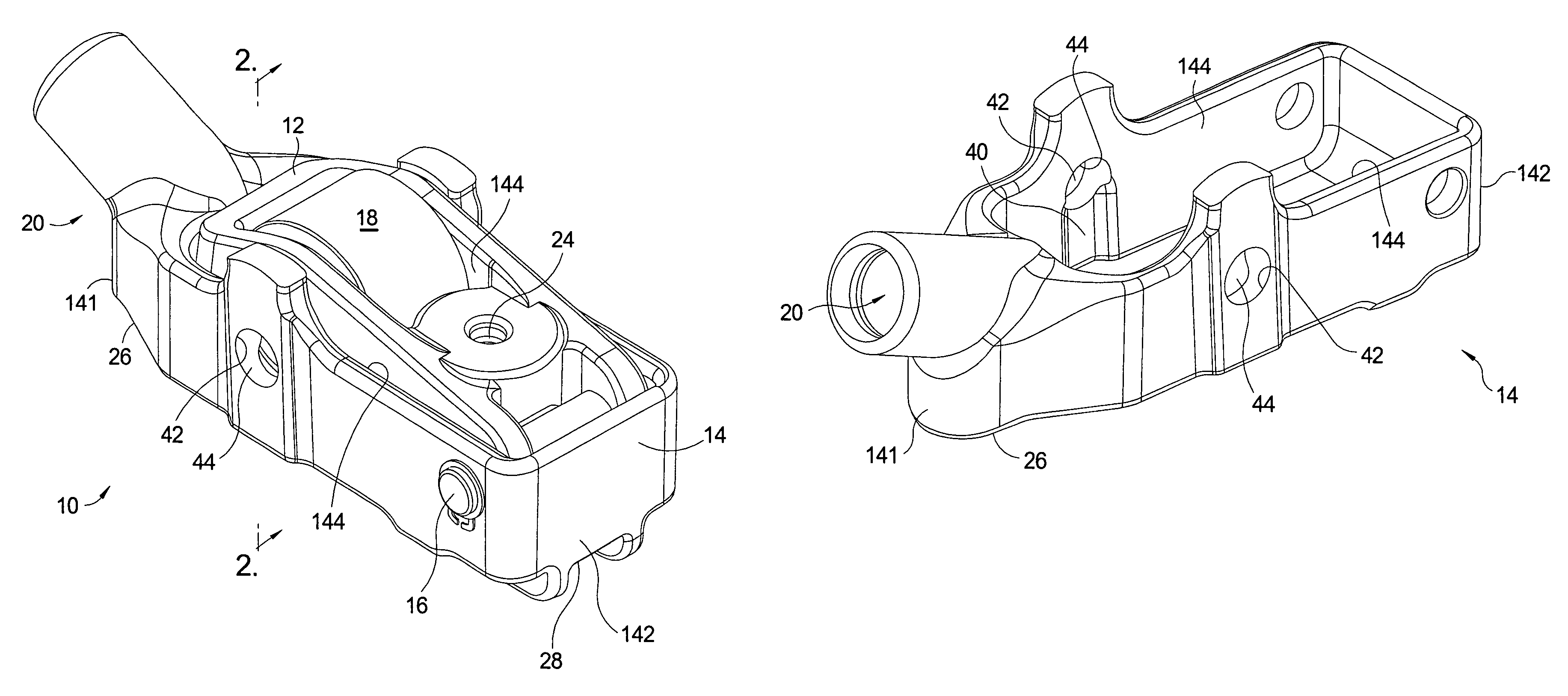
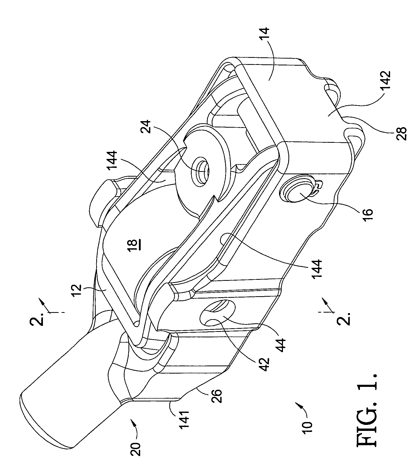
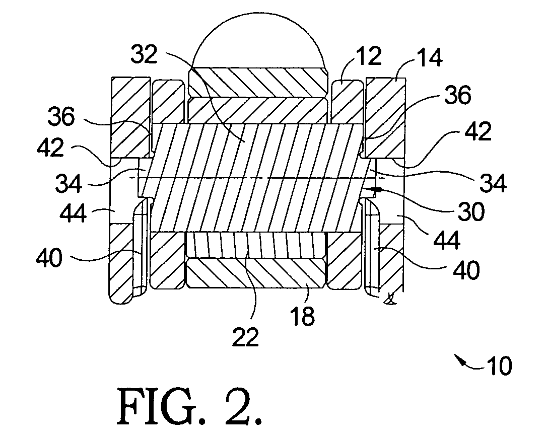
[0024]Referring to FIGS. 1 and 2, a deactivation RFF assembly 10 in accordance with the invention is illustrated. While this invention is described in the context of a switchable deactivation RFF, it should be understood that the inner arm stop as described below may be applied to a switchable two-step RFF as well.

[0025]Switchable deactivation RFF assembly 10 includes an inner arm 12 that is pivotably and therefore deactivateably disposed in a central opening in an outer arm 14. Inner arm 12 pivots within outer arm 14 about a pivot shaft 16. Inner arm 12 includes a contact surface. The contact surface may be a roller 18 carried by a shaft 30 that is supported by the inner arm 12. A bearing 22 may rotatably support roller 18 on shaft 30 for following a cam lobe of a lifting cam of an engine camshaft (not shown). Bearing 22 may be, for example, a roller or needle bearing. Shaft 30 may or may not be fixed from rotation with inner arm 12. In the case where the contact surface does not i...


PUM


Abstract

A roller finger follower assembly for variably activating a valve in an internal combustion engine includes at least one vertical recessed channel formed inside an outer arm and a shaft. The channel includes a machined upper surface closing the channel. The shaft engages with the recessed channel, the shaft reciprocates within the recessed channel, and the upper surface stops an upward movement of the shaft.

Description

TECHNICAL FIELD[0001]The present invention relates to mechanisms for altering the actuation of valves in internal combustion engines; more particularly, to a switchable rocker arm such as a roller finger follower capable of changing between high and low or no valve lifts; and most particularly, to a stop for limiting the upward travel of an inner arm of a switchable rocker arm.BACKGROUND OF THE INVENTION[0002]Variable valve activation (VVA) mechanisms for internal combustion engines are well known. It is known to lower the lift, or even to provide no lift at all, of one or more valves of a multiple-cylinder engine, during periods of light engine load. Such valve deactivation or valve lift switching can substantially improve fuel efficiency.[0003]A Roller Finger Follower (RFF), as a type of rocker arm, acts between a rotating eccentric camshaft lobe and a pivot point on the engine, such as a Hydraulic Lash Adjuster (HLA), to open and close an engine valve. Switchable RFFs may be a “d...

Claims


Application Information

Patent Timeline
Patent Type & Authority Patents(United States)
IPC IPC(8): F01L1/18
CPCF01L1/185F01L13/0005F01L13/0015Y10T74/20882F01L2105/00F01L2105/02F01L2305/02F01L2305/00
Inventor SPATH, MARK J.HENDRIKSMA, NICK J.MCCARROLL, MICHAEL E.
Owner DELPHI TECH IP LTD
Learn More