
Gear drive unit

a gear drive and gear drive technology, applied in the direction of gearing, dynamo-electric machines, dynamo-electric components, etc., can solve the problems of undone connection between the armature shaft and the worm pressing on it, and achieve the effect of reducing the force necessary for pressing the effect of installation

Inactive Publication Date: 2011-02-08
ROBERT BOSCH GMBH
View PDF20 Cites 5 Cited by
  • Summary
  • Abstract
  • Description
  • Claims
  • Application Information

AI Technical Summary

Benefits of technology

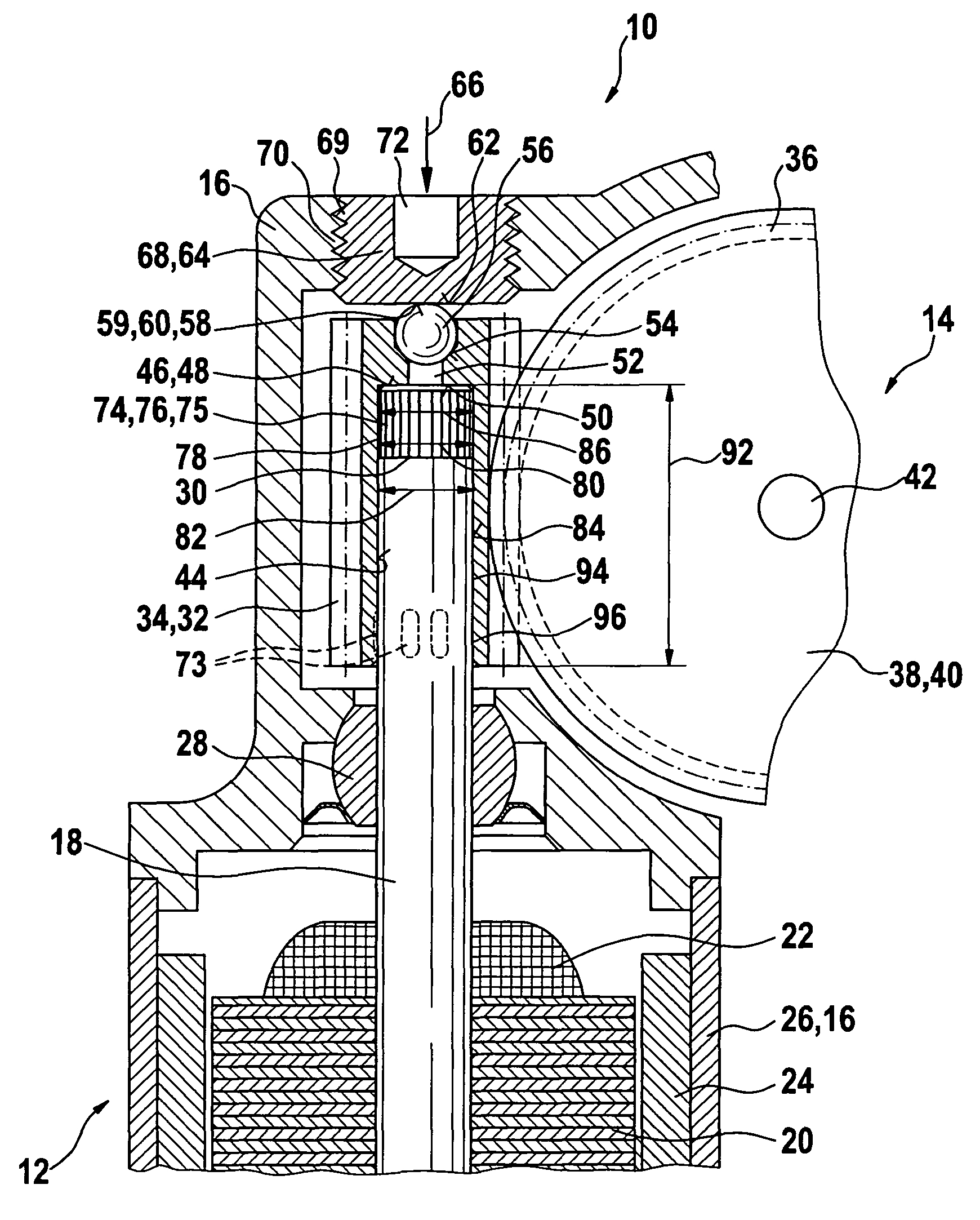
The invention is an apparatus for reducing friction and increasing efficiency in a drive unit. It includes an axial bearing face on the toothed element supported on the rotor shaft, which helps to dissipate strong axial forces acting on the toothed element. The toothed element is braced axially on the housing, and the connection between the toothed element and the rotor shaft needs to divert only the torque acting on the housing. The bearing face is especially favorably embodied as a curved face braced virtually at a point on a flat corresponding face connected to the housing. The bracing face is especially favorably embodied as a curved face braced virtually at a point on a flat corresponding face connected to the housing. The toothed element is fixed on the rotor shaft in a manner that is fixed against relative rotation, and the connection is especially suitable for use in a worm gear. The technical effects of the invention include reduced friction, increased efficiency, and simplified assembly of toothed elements.

Problems solved by technology

Especially if the part to be adjusted strikes a stop, strong, sudden axial forces act on the worm, and as a result the connection between the armature shaft and the worm pressed onto it may come undone.

Method used


Image

  • Gear drive unit
  • Gear drive unit

Examples


Embodiment Construction

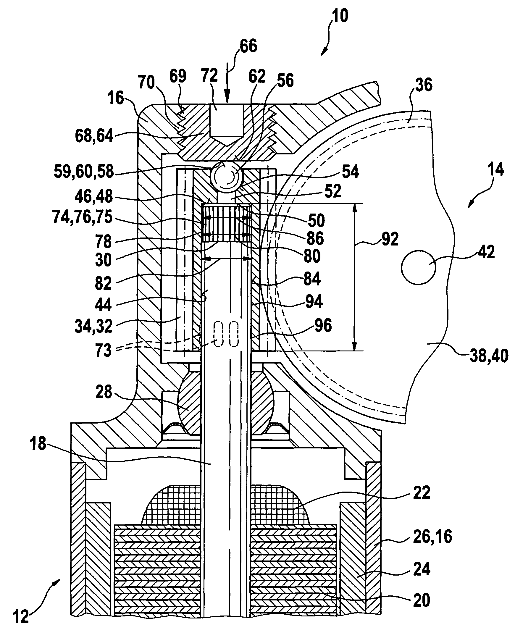
[0017]In FIG. 1, a gear drive unit 10 is shown, having an electric motor and a gear 14 and a multi-part housing 16 surrounding it. The electric motor 12 has an armature packet 20 that is supported on a rotor shaft 18 and has electrical windings 22. These windings cooperate with magnets 24, which are located in a housing part 16 embodied as a pole cup 26. The rotor shaft 18 is supported here by means of slide or roller bearings 28 in the housing 16 and with one end 30, it extends into the region of the gear 14. A toothed element 32 is located on the rotor shaft 18; in this exemplary embodiment, it is embodied as a worm 34. The toothed element 32 meshes with a toothing 36 of a gear element 38, which is embodied here as a worm wheel 40 and is supported on a bolt 42 structurally connected to the housing. The gear element 38 is connected to a movable final control element, not shown in detail, which for instance adjusts seats in the motor vehicle. The toothed element 32 is manufactured a...


PUM


Abstract

In a gear drive unit (10), in particular for adjusting moving parts in the motor vehicle, having a rotor shaft (18) supported in a housing (16) and braced axially on the housing (16) via at least one face end (50) and in which a separate toothed element (32) for transmitting torque to a gear component (38, 40) is secured to the rotor shaft (18), the toothed element (32) has an axial bearing face (48) that rests on one of the face ends (50) of the rotor shaft (18).

Description

BACKGOROUND OF THE INVENTION[0001]The invention relates to a gear drive unit, particularly for adjusting moving parts in the motor vehicle.[0002]One such drive unit has become known from German Utility Model DE 297 02 525 U1; in it, an electric drive motor is operatively connected to a gear located downstream, via an armature shaft. The armature shaft is supported in multiple places in a multi-part housing and extends as far as into the region of the gear. A worm communicating with a worm wheel is pressed onto the armature shaft. On its face ends, the armature shaft is braced on the housing via both run up disks and a damping means.[0003]In such a drive mechanism, used for instance for power windows or for a seat adjuster, forces in both the radial direction and the circumferential direction as well as the axial direction act on the worm. Especially if the part to be adjusted strikes a stop, strong, sudden axial forces act on the worm, and as a result the connection between the arma...

Claims


Application Information

Patent Timeline
Patent Type & Authority Patents(United States)
IPC IPC(8): F16H1/16H02K7/08
CPCH02K7/081Y10T74/18792Y10T74/19828H02K7/116H02K7/08
Inventor SCHWENDEMANN, FRANZ
Owner ROBERT BOSCH GMBH
Learn More