Limited perimeter vector matching fault localization protocol for survivable all-optical networks

a fault localization and perimeter vector technology, applied in data switching networks, frequency-division multiplexes, instruments, etc., can solve the problems of increasing affecting the service life of components, and affecting the reliability of fault localization, so as to reduce the computational complexity of localizing faults, preserve high-bandwidth, and high-speed and efficient

Inactive Publication Date: 2011-02-01
OTTAWA UNIV OF
View PDF12 Cites 0 Cited by
  • Summary
  • Abstract
  • Description
  • Claims
  • Application Information

AI Technical Summary

Benefits of technology

[0027]According to the present invention, the fault localization method and system can be performed on all types of networks. For example, in an all-optical network, fault localization can be accomplished in the optical layer via end-nodes. This is mainly to preserve the high-bandwidth of all-optical communications. At the outset, the present invention assumes that significant factors for having effective fault localization in the optical layer have been properly taken care of. Such factors include: influences due to nonlinearities, dispersion, and wavelength-to-wavelength interactions that are not wrongly reported as an interruption of service; transporting the optical signals from one provider domain to another, and monitoring different signal parameters is done with the same accuracy i.e. interoperability is fully achieved.
[0028]In order to provide the maximum level of transparency, the present invention does not necessarily involve any optical power monitoring or spectrum analysis at intermediate nodes. Accordingly, the method of the present invention is activated when a set of alarming sinks emerges in the system. In a preferred embodiment, the fault localization method of the present invention is implemented by means of several distinct phases: pausing, flooding, multicasting, matching, and concluding phases, not all of which may be used to decrease the computational complexity of localizing the fault.

Problems solved by technology

However, their components are still exposed to a variety of service disruptions, including hard and soft failures with long or very short time intervals.
Despite the fact that soft and intermittent failures are the most frequent ones in this type of network, hard failures with long disconnection time are the most destructive.
In terms of hard failures, cable-cuts are more prevalent than switch-crashes since optical cables are extended widely and subsequently have a higher likelihood of exposure to environmental damages.
In transporting a high volume of data, any severed Wavelength Division Multiplexed (WDM) link can lead to the loss of several terabits per second.
Consequently, the network performance can be harshly degraded and the robustness of the network can be shattered.
However, the following comparisons highlight some of the drawbacks of methods and systems for fault localization and restoration known in the prior art.
Consequently, link restoration decreases the number of to-be-reconfigured switches and increases the probability of success.
However, link restoration can create a congested area around the failed link or cause long restoration loops.
While the latter phenomenon could severely alter the protocol functionality of link restoration, typically this only happens in highly loaded networks.
The fault localization time for a larger network can be considerable and undesirable.
However, at the expense of the fault localization delay, network routing tables are validated and the restoration is completed faster.
However, path restoration can be time-consuming for distant Source-Destination (S-D) pairs or in heavily loaded networks.
Some all-optical components, such as Optical Amplifiers (OA), have limited or no electronic monitoring and analysis abilities.
As a result, they may be able to detect loss of signal but cannot define high Bit Error Rate (BER) and / or manage any fault localization procedures.
Despite the fact that centralized control mechanisms are relatively simple and work well for static traffic in small networks, they are not considered to be feasible for dynamic expanding systems.
In contrast, distributed control mechanisms are complex but more scalable and reliable than the centralized ones.
However, hierarchical management models cannot be economically and practically implemented for all network topologies.
However, their implementation is substantially different.
However, fault localization in SONET involves examining overhead at each node, which slows down the fault localization procedure.
Although digital wrapper greatly improves the BER, it also consumes bandwidth by approximately 7% and suffers from related delay.
However, the controlling bandwidth usage is considerable.
December 2004 that the protocol outperforms segmented restoration protocol in terms of time delay, overhead and complexity.
However, the time and space complexity of protocol could be considerable for large networks.
1784-1793, October 1997, but its computational complexity for large-scale and dynamic networks impedes its deployment.

Method used


Image

  • Limited perimeter vector matching fault localization protocol for survivable all-optical networks
  • Limited perimeter vector matching fault localization protocol for survivable all-optical networks
  • Limited perimeter vector matching fault localization protocol for survivable all-optical networks

Examples


Embodiment Construction

[0102]The invention will be described for the purposes of illustration only in connection with certain embodiments. However, it is to be understood that other objects and advantages of the present invention will be made apparent by the following description of the drawings according to the present invention. While a preferred embodiment is disclosed, this is not intended to be limiting. Rather, the general principles set forth herein are considered to be merely illustrative of the scope of the present invention and it is to be further understood that numerous changes may be made without straying from the scope of the present invention.

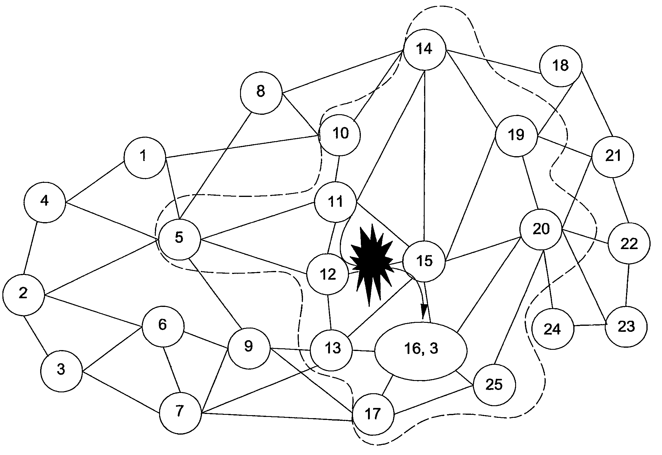
[0103]The present invention provides a protocol, referred to hereinafter as the Limited perimeter Vector Matching fault localization protocol (LVM). It is assumed that each fiber is multiplexed in the applied network. As such, the number of lightpaths traversing a link could be as large as the wavelength multiplexing degree. In general, once such a lin...


PUM


Abstract

The inventive Limited perimeter Vector Matching fault localization method and system is launched when alarming sinks are identified. Each alarming sink broadcasts its node ID and path length, and all nodes compare their paths to identify an executive sink, which creates an Affected Link Vector consisting of the links in its lightpath, for multicast within a limited perimeter thereabout, the perimeter comprising all nodes within a neighborhood size. Each recipient returns an outcome vector corresponding to the ALV, together with a status, which indicate if the corresponding lightpath is healthy. For failed lightpaths, corresponding cells of the binary vector are set and cleared otherwise. For healthy lightpaths, bits are inverted. The vectors are ANDed by the executive sink to identify the disconnection. The exercise could be repeated for a progressively larger limited perimeter. The affected path is restored by link restoration. Multiple fault localization exercises may be simultaneously performed.

Description

CROSS REFERENCE TO RELATED APPLICATIONS[0001]This application claims the benefit of Canadian Patent Application Serial No. 2,543,417, filed Apr. 13, 2006, which disclosure is incorporated herein by reference in its entirety.FIELD OF THE INVENTION[0002]The present invention relates to methods and systems for fault localization in data networks. More particularly, the present invention relates to fault localization in all-optical networks.BACKGROUND TO THE INVENTION[0003]Today, optical networks have established themselves as powerful high-bandwidth communication networks. However, their components are still exposed to a variety of service disruptions, including hard and soft failures with long or very short time intervals. Despite the fact that soft and intermittent failures are the most frequent ones in this type of network, hard failures with long disconnection time are the most destructive. In terms of hard failures, cable-cuts are more prevalent than switch-crashes since optical c...

Claims


Application Information

Patent Timeline
Patent Type & Authority Patents(United States)
IPC IPC(8): H04L12/26
CPCH04J14/0227H04L41/0677H04Q11/0062H04J14/0284H04Q2011/0073H04Q2011/0081
Inventor SICHANI, ATOUSA VALIMOUFTAH, HUSSEIN T.
Owner OTTAWA UNIV OF
Why Eureka
Try Eureka