
Electrical floor access module system

a technology of floor access module and electrical floor, which is applied in the direction of substation/switching arrangement casing, installation of lighting conductors, coupling device connections, etc., to achieve the effect of convenient removal of system components and convenient rearrangement of overall system configuration

Active Publication Date: 2011-02-01
BYRNE NORMAN R
View PDF41 Cites 30 Cited by
  • Summary
  • Abstract
  • Description
  • Claims
  • Application Information

AI Technical Summary

Benefits of technology

"The invention is an electrical system that can be easily installed under an access floor and is adaptable to different types of electrical devices. The system includes interconnected modules that allow for easy rearrangement and removal of components. The system also includes receptacle blocks that can be interchanged with each other, without requiring any tools or equipment. The system can be used as a modular system, with interconnected components that can be easily installed and reconfigured. The system also includes cover means for the access floor modules, as well as means for extending cables from the modules. The system is designed to provide power to various types of electrical devices and can be easily installed and reconfigured."

Problems solved by technology

The previously described electrical floor access module systems, in view of their configurations, comprise certain limitations with respect to positioning of electrical receptacle blocks, ease of access to such blocks for interchanging the same, and similar limitations.
Also, the previously described embodiments do not incorporate any particular means for wire management, or means for covering the access floor modules.

Method used


Image

  • Electrical floor access module system
  • Electrical floor access module system
  • Electrical floor access module system

Examples


Embodiment Construction

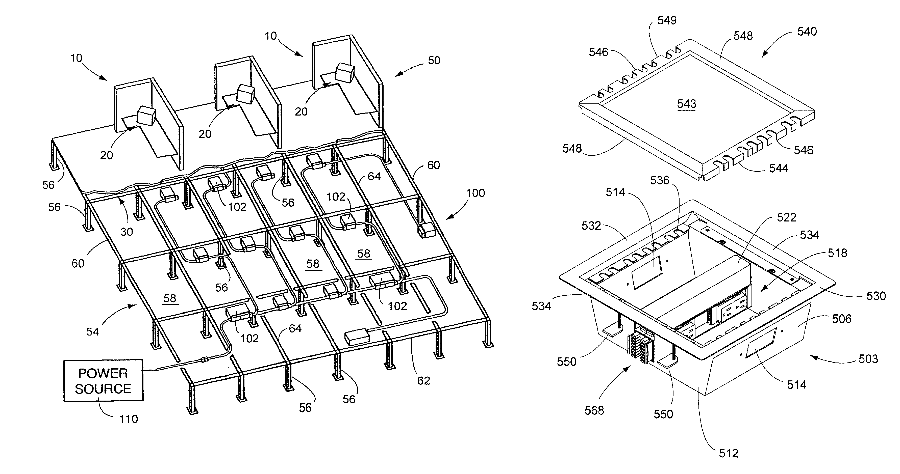
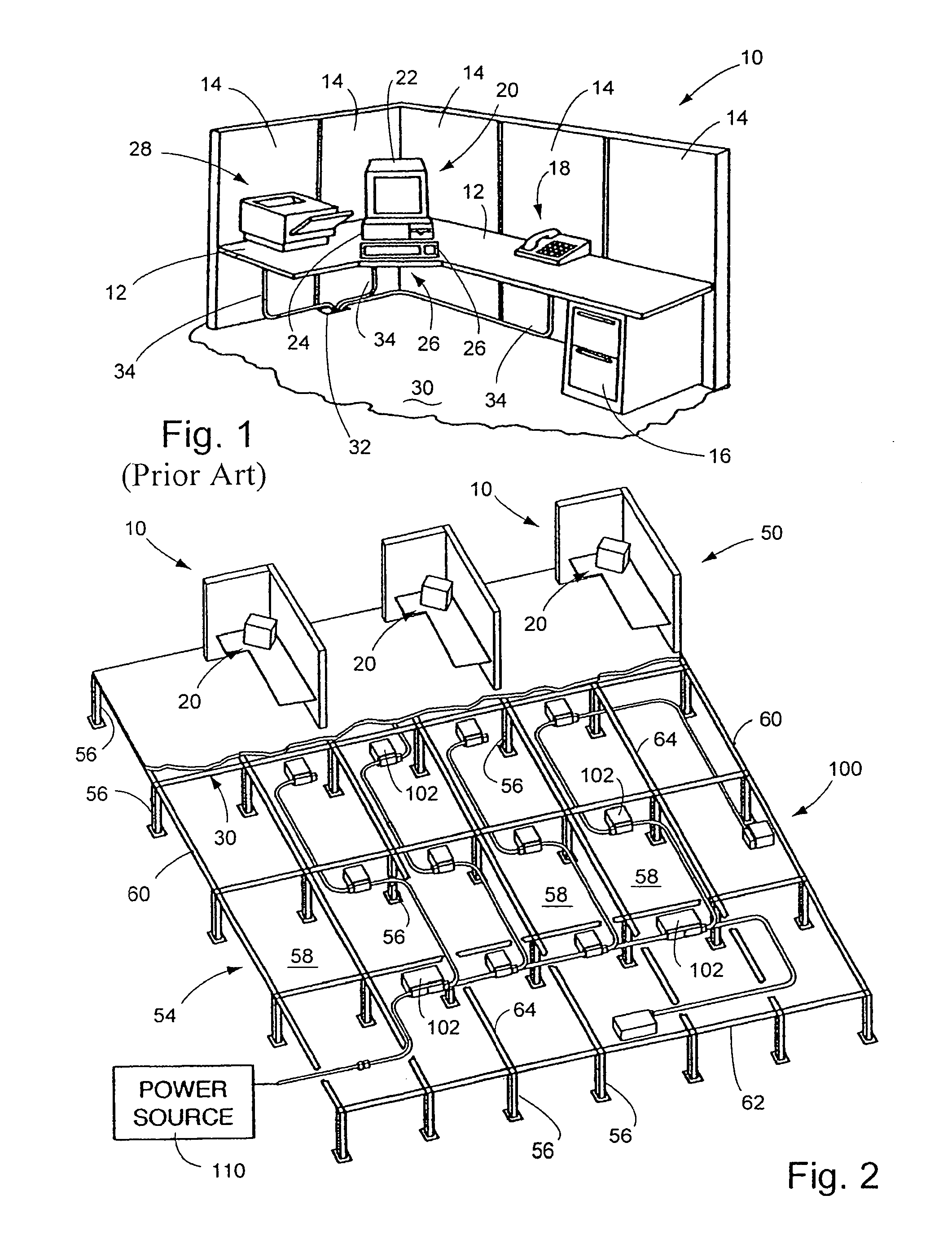
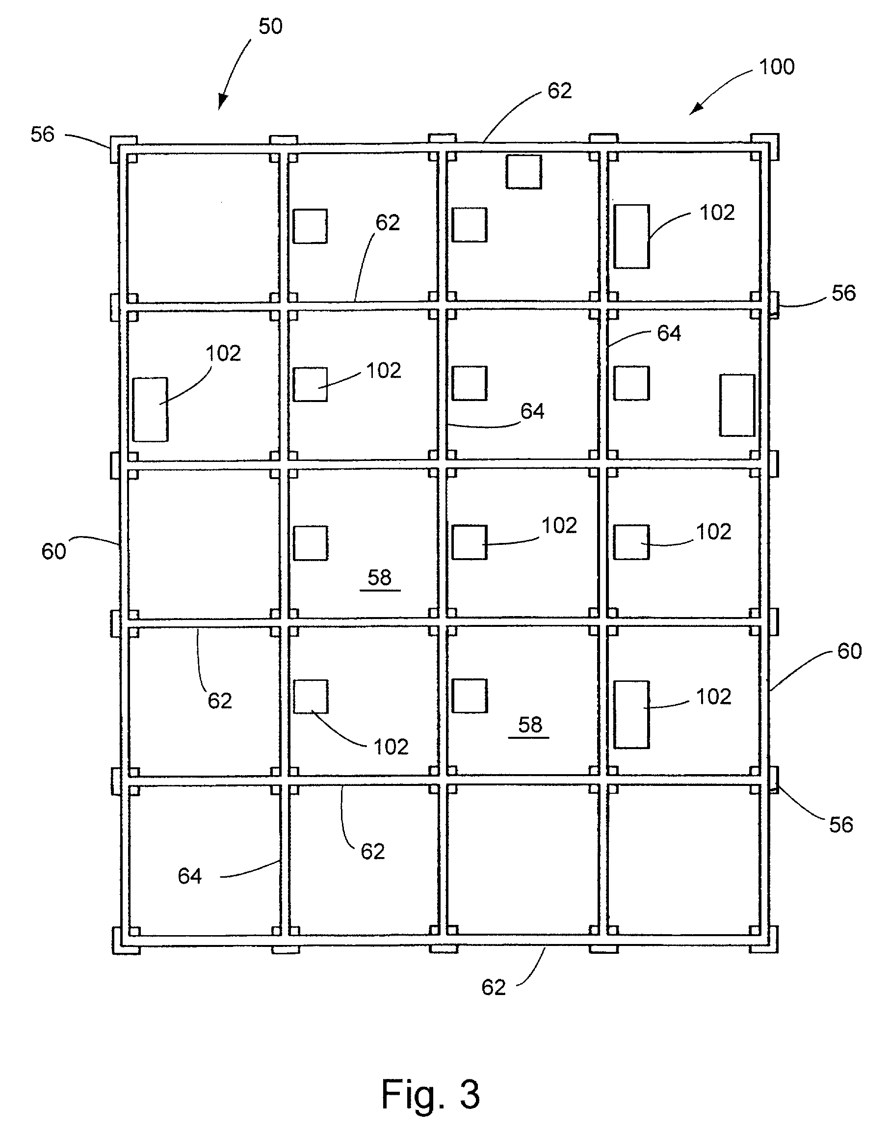
[0071]The principles of the invention are disclosed, by way of example, in several embodiments directed to electrical access floor systems, is depicted in FIGS. 1-35. In particular, the preferred embodiment of an electrical access floor system in accordance with the invention as described herein comprises the system 500 primarily illustrated in FIGS. 16-35. The electrical access floor systems provide for readily accessible access floor modules having means for selectively mounting and positioning electrical receptacle outlets, communications outlets and similar devices. The floor access system also provides for facilitating interconnection of cables and receptacles without hard-wired interconnections. In addition, the electrical access floor system uses a relatively minimum number of different types of electrical components and readily provides component interchangeability and facilitates system reconfiguration.

[0072]Still further, an electrical system in accordance with the inventi...


PUM


Abstract

An electrical system (500) is positioned beneath an access floor (30) and includes a number of access floor modules (502) for providing electrical power locations for energizing electrical devices. Cable assemblies (578) electrically interconnect the modules (502) to the power source and to each other. Junction blocks (518) are mechanically connected to the access floor modules (502). Electrical receptacle blocks (562) are electrically interconnected to the junction blocks (518) for supplying power to interconnected electrical devices.

Description

CROSS-REFERENCE TO RELATED APPLICATIONS[0001]Not applicable.STATEMENT REGARDING FEDERALLY SPONSORED RESEARCH OR DEVELOPMENT[0002]Not applicable.REFERENCE TO MICROFICHE APPENDIX[0003]Not applicable.BACKGROUND OF THE INVENTION[0004]1. Field of the Invention[0005]The invention relates to electrical power systems, and more particularly, to power systems having modules positioned beneath access flooring structures and the like.[0006]2. Background Art[0007]The use of computers, sophisticated telecommunications equipment and other electronic devices is continuing to rapidly increase in commercial, industrial and other office environments. As a result, the importance of efficiently supplying power throughout these environments is also increasing. In particular, the use of modular office systems, with movable workstations and interior walls, has led to electrical systems far different and more sophisticated than the conventional designs comprising single or double unit electrical receptacles...

Claims


Application Information

Patent Timeline
Patent Type & Authority Patents(United States)
IPC IPC(8): H02G3/08E04B5/00
CPCE04F15/024H02G3/385
Inventor BYRNE, NORMAN R.
Owner BYRNE NORMAN R
Learn More