
Multiple burner arrangement for operating a combustion chamber, and method for operating the multiple burner arrangement

Active Publication Date: 2011-02-01
GENERAL ELECTRIC TECH GMBH
View PDF13 Cites 4 Cited by
  • Summary
  • Abstract
  • Description
  • Claims
  • Application Information

AI Technical Summary

Benefits of technology

The object on which the invention is based is to develop a multiple burner arrangement with a multiplicity of individual burners designed as premix burners, in particular for operating a gas turbine plant, according to the preamble of claim 1, in such a way that the operation of a multiplicity of individual premix burners can be optimized as flexibly or variably as possible as a function of the respective load state and of the parameters influencing the combustion process, as mentioned above. In particular, it is expedient to provide a regulating possibility which optimizes the operation of a multiple burner arrangement in terms of pollutant emission and which markedly reduces the pulsations caused by combustion over the entire load range.
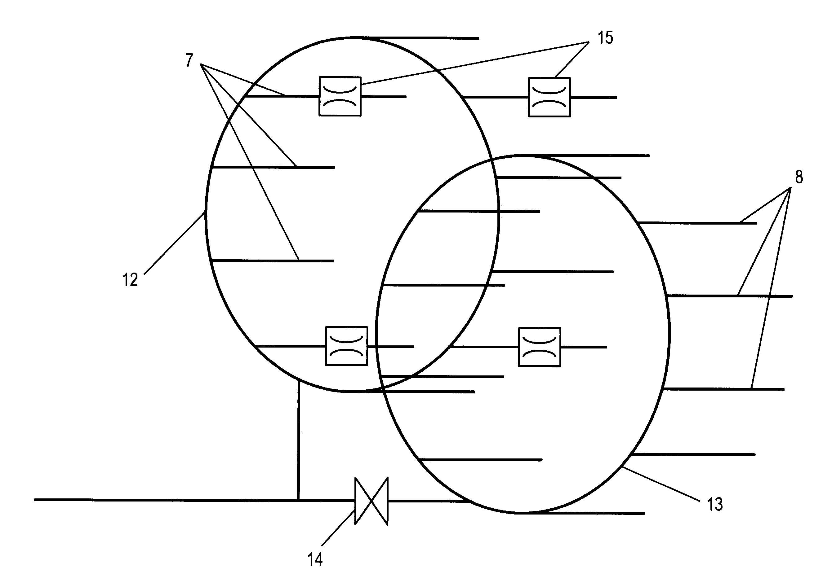
The multiple burner arrangement according to the invention emphasizes the deliberate use of premix burner systems which can be operated in a staged manner and which have means for internally staged fuel injection into the swirl space for premix operation. For this purpose, each individual premix burner provided in the multiple burner arrangement is supplied with fuel, preferably gaseous fuel, via at least two separate fuel lines, a first and a second fuel line, as they are known, by means of which the fuel is fed into the swirl space for the further formation of the swirl flow. The in each case first fuel line of each premix burner is connected to a first ring line, via which the in each case first fuel lines of all the premix burners within the multiple burner arrangement are supplied with fuel. Furthermore, a second ring line is provided, which is connected in each case to the second fuel line of each individual premix burner provided in the multiple burner arrangement. It is essential, then, that, in the case of a first group of premix burners, the selected number of which is preferably smaller than half the total number provided in the multiple burner arrangement, a regulating unit, for example a throttle valve, influencing the fuel supply is provided in at least one of the fuel lines. By means of a regulated throttling of the fuel supply with respect to a selected group of premix burners, on the one hand, it is possible to provide a deliberately asymmetric temperature profile along an annular premix burner arrangement, for example within the framework of an annular combustion chamber arrangement, and thus effectively to counteract the burner-induced thermoacoustic oscillations, and, on the other hand, the regulatable fuel throttling allows an individual coordination of the burner behavior with basically all the parameters influencing the combustion process.
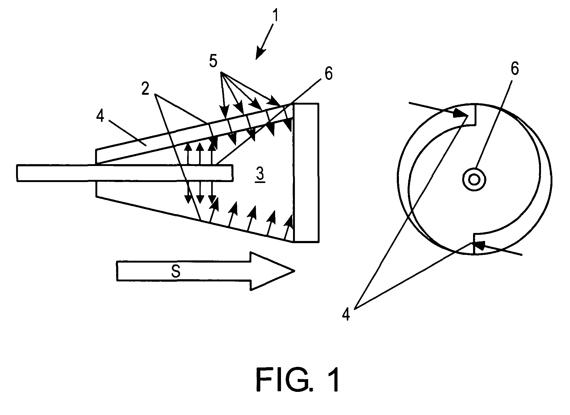
When premix burners with a burner lance at least partially penetrating centrally through the swirl space are used, in starting operation or in the lower load range of the gas turbine a large part of the preferably gaseous fuel is fed into the swirl space via the burner lance. For this purpose, in each case, the burner lances are connected to the in each case first fuel line, these being fed with fuel in each case by a common ring line. By contrast, in the medium and upper load range, the multiple burner arrangement is operated in such a way that markedly more than half the gaseous fuel is supplied, in each case via the second fuel line, to the premix burners via the fuel outlet ports which extend along the air inlet slots. This is made possible by the connection of the fuel supply via the second ring line from which the in each case second fuel lines of the individual premix burners are fed, the fuel feed via the first ring line being throttled, as required. The advantage of this is that, independently of the operating point of the gas turbine plant, an ideal air / fuel mixture can always be generated in which the individual fuel stages are supplied differently with fuel as a function of the load range of the gas turbine plant and an optimum of the combustion behavior in terms of pollutant emissions and pulsation behavior can thereby be achieved, with the result that the operating range of the gas turbine can be extended substantially.
Independently of the respective embodiment of the premix burners used and of the fuel supply ratio, capable of being set by the load state, between the ring lines and the first and second fuel lines connected to these, the burner concept according to the invention makes it possible, by providing additional regulating units along the fuel lines branching off from a ring line, to have, only in the case of a selected group of premix burners provided in the multiple burner arrangement, a deliberate break-up of symmetry in the temperature distribution along the flame forming within the combustion chamber, with the result that a decisive influence can be exerted on the reduction of thermoacoustic oscillations generated within the combustion chamber. The regulating units, provided in the fuel lines and preferably designed as throttle valves, likewise allow an active regulation or control as a function of parameters influencing the combustion process, such as, for example, the moisture fraction, varying as a function of the load range of the gas turbine arrangement, in the combustion supply air, the ambient temperature, the change in fuel composition and also the aging of gas turbine components.

Problems solved by technology

In both instances, fuel is administered directly into the flow zone required for flame stabilization, but, in terms of pollutant emission, burns in an extremely unfavorable mixture ratio under virtually stoichiometric conditions.
Technically complicated scavenging methods are required for this purpose.
Moreover, the changeover actions from pilot operation to premix operation, or vice versa, are undesirable, since these excite burner-internal pulsations which, depending on their markedness, subject the plant components involved in the combustion process to high mechanical load.
Furthermore, thermoacoustic oscillations of this type preferentially also arise in premix operation, that is to say in the medium and upper load range, due to which the flame stability forming within the combustion chamber is seriously impaired.
It is shown, however, that, under different load conditions of the gas turbine plant, operating ranges occur in which high combustion chamber pulsations, a poor burn-out and associated high carbon oxide values and also high values of unsaturated hydrocarbons arise and in which a poor transverse ignition behavior of the individual premix burners can be observed.
Although this measure contributes to the damping of pulsations in the upper load range of the gas turbine plant which are usually in resonant form and rotate circularly in an annular combustion chamber, nonetheless limits are placed on further influence on the burner behavior in terms of the operation of the gas turbine plant in different load states and taking into account other parameters influencing the combustion processes within the respective premix burners, such as, for example, highly varying moisture fractions in the combustion supply air in the case of an increase in power output of the gas turbine, ambient temperature, change in fuel composition and also aging phenomena of the overall gas turbine plant.
Moreover, the proposal described above does not allow any subsequent retrofittability on already existing gas turbine plants, and therefore the known measure can be implemented solely in gas turbine plants to be newly procured.

Method used


Image

  • Multiple burner arrangement for operating a combustion chamber, and method for operating the multiple burner arrangement
  • Multiple burner arrangement for operating a combustion chamber, and method for operating the multiple burner arrangement
  • Multiple burner arrangement for operating a combustion chamber, and method for operating the multiple burner arrangement

Examples


Embodiment Construction

The object on which the invention is based is to develop a multiple burner arrangement with a multiplicity of individual burners designed as premix burners, in particular for operating a gas turbine plant, according to the preamble of claim 1, in such a way that the operation of a multiplicity of individual premix burners can be optimized as flexibly or variably as possible as a function of the respective load state and of the parameters influencing the combustion process, as mentioned above. In particular, it is expedient to provide a regulating possibility which optimizes the operation of a multiple burner arrangement in terms of pollutant emission and which markedly reduces the pulsations caused by combustion over the entire load range.

The solution for achieving the object on which the invention is based is specified in claim 1. The subject of claim 8 is a method for operating a multiple burner arrangement, such as is suitable, for example, for operating an annular combustion cha...


PUM


Abstract

What are described are a multiple burner arrangement and a method for operating such a multiple burner arrangement with a multiplicity of individual burners which are designed as premix burners and which serve for firing a combustion chamber of a thermal engine and each have a swirl space into which combustion supply air and fuel can be introduced so as to form a swirl flow, the swirl flow forming downstream of the premix burner, within the combustion chamber, a backflow zone in which a burner flame is formed.

Description

BACKGROUNDA multiple burner arrangement is disclosed with a multiplicity of individual burners which are designed as premix burners and which serve for firing a combustion chamber for a thermal engine, preferably for a gas turbine plant, and each have a swirl space into which combustion supply air and fuel are fed so as to form a swirl flow, the swirl flow forming downstream of the premix burner, within the combustion chamber, a backflow zone which forms spatially in a largely stable manner and in which a burner flame is formed after the ignition of the fuel / air mixture. A method for operating a multiple burner arrangement of this type is likewise described.Multiple burner arrangements have gained acceptance not least because of ecological factors, since the formation of nitrogen oxides in the exhaust gases can be kept low on account of a low flame temperature along with a high air excess. In this connection, in particular, it has become possible for annular combustion chambers, as ...

Claims


Application Information

Patent Timeline
IPC IPC(8): F23D14/46F02C7/228F23K5/06F23R3/28F23R3/34
CPCF23K5/06F23R3/286F23R3/346
Inventor FLOHR, PETERMOTZ, CHRISTIAN JOERGTOQAN, MAJEDZAJADATZ, MARTIN
Owner GENERAL ELECTRIC TECH GMBH
Learn More