
Micro-electromechanical system based arc-less switching with circuitry for absorbing electrical energy during a fault condition

a micro-electromechanical system and circuitry technology, applied in the field of micro-electromechanical system based switching devices, can solve the problems of large circuit breakers, large circuit breakers, and general slow speed of circuit breakers, and achieve the effect of suppressing arc formation

Active Publication Date: 2011-01-25
GENERAL ELECTRIC CO
View PDF14 Cites 7 Cited by
  • Summary
  • Abstract
  • Description
  • Claims
  • Application Information

AI Technical Summary

Benefits of technology

The MEMS switch effectively suppresses arc formation and minimizes heat generation, enabling fast and efficient switching with reduced energy dissipation and improved safety.

Problems solved by technology

Traditionally, most conventional circuit breakers include bulky electromechanical switches.
Unfortunately, these conventional circuit breakers are large in size thereby necessitating use of a large force to activate the switching mechanism.
Additionally, the switches of these circuit breakers generally operate at relatively slow speeds.
Furthermore, these circuit breakers are disadvantageously complex to build and thus expensive to fabricate.
Moreover, energy associated with the arc may seriously damage the contacts and / or present a burn hazard to personnel.
However, since solid-state switches do not create a physical gap between contacts when they are switched into a non-conducing state, they experience leakage current.
Furthermore, due to internal resistances, when solid-state switches operate in a conducting state, they experience a voltage drop.
Both the voltage drop and leakage current contribute to the generation of excess heat under normal operating circumstances, which may be detrimental to switch performance and life.
Moreover, due at least in part to the inherent leakage current associated with solid-state switches, their use in circuit breaker applications is not possible.

Method used


Image

  • Micro-electromechanical system based arc-less switching with circuitry for absorbing electrical energy during a fault condition
  • Micro-electromechanical system based arc-less switching with circuitry for absorbing electrical energy during a fault condition
  • Micro-electromechanical system based arc-less switching with circuitry for absorbing electrical energy during a fault condition

Examples


exemplary embodiment 96

[0048]FIG. 6 illustrates an exemplary embodiment 96 wherein the switching circuitry 12 (see FIG. 1) may include multiple MEMS switches arranged in a series or series-parallel array, for example. Additionally, as illustrated in FIG. 6, the MEMS switch 20 may replaced by a first set of two or more MEMS switches 98, 100 electrically coupled in a series circuit. In one embodiment, at least one of the first set of MEMS switches 98, 100 may be further coupled in a parallel circuit, where the parallel circuit may include a second set of two or more MEMS switches (e.g., reference numerals 100, 102). In accordance with aspects of the present invention, a static grading resistor and a dynamic grading capacitor may be coupled in parallel with at least one of the first or second set of MEMS switches.

exemplary embodiment 104

[0049]Referring now to FIG. 7, an exemplary embodiment 104 of a graded MEMS switch circuit is depicted. The graded switch circuit 104 may include at least one MEMS switch 106, a grading resistor 108, and a grading capacitor 110. The graded switch circuit 104 may include multiple MEMS switches arranged in a series or series-parallel array as for example illustrated in FIG. 6. The grading resistor 108 may be coupled in parallel with at least one MEMS switch 106 to provide voltage grading for the switch array. In an exemplary embodiment, the grading resistor 108 may be sized to provide adequate steady state voltage balancing (division) among the series switches while providing acceptable leakage for the particular application. Furthermore, both the grading capacitor 110 and grading resistor 108 may be provided in parallel with each MEMS switch 106 of the array to provide sharing both dynamically during switching and statically in the OFF state. It may be noted that additional grading r...


PUM


Abstract

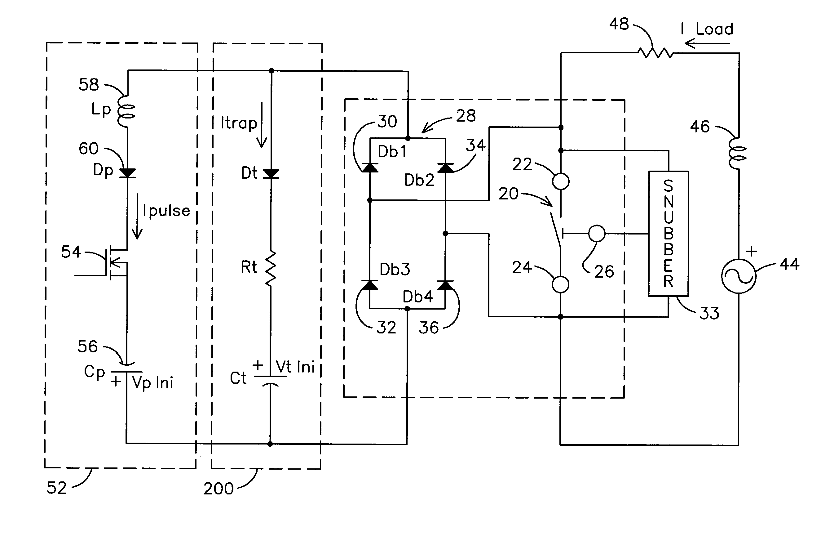
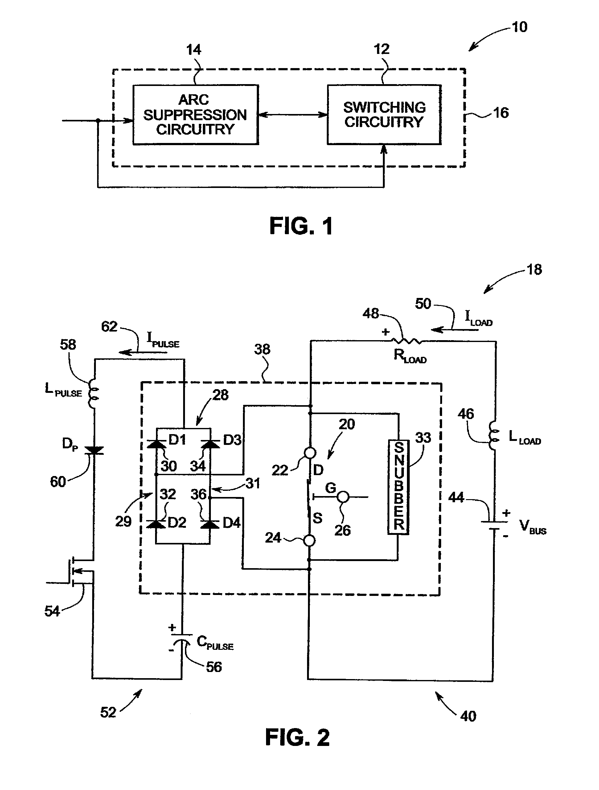
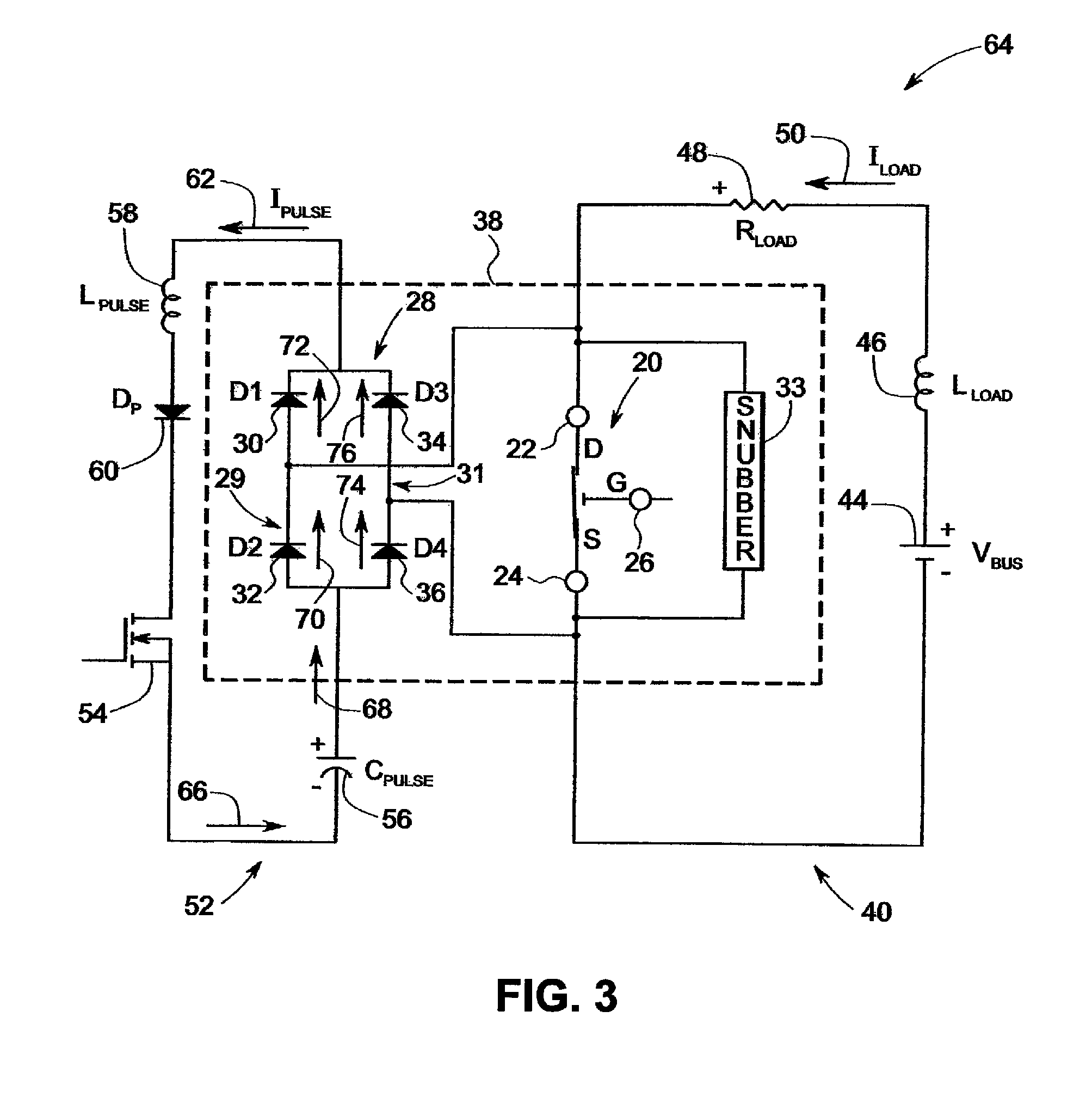
A system is presented. The system includes a micro-electromechanical system switch. Further, the system includes a balanced diode bridge configured to suppress arc formation between contacts of the micro-electromechanical system switch. A pulse circuit is coupled to the balanced diode bridge to form a pulse signal in response to a fault condition. An energy-absorbing circuitry is coupled in a parallel circuit with the pulse circuit and is adapted to absorb electrical energy resulting from the fault condition without affecting a pulse signal formation by the pulse circuit.

Description

RELATED APPLICATIONS[0001]The present application is a continuation-in-part of U.S. patent application Ser. No. 11 / 314,336 filed on Dec. 20, 2005, which is incorporated by reference in its entirety herein.BACKGROUND[0002]Embodiments of the invention relate generally to a switching device for switching off a current in a current path, and more particularly to micro-electromechanical system based switching devices.[0003]A circuit breaker is an electrical device designed to protect electrical equipment from damage caused by faults in the circuit. Traditionally, most conventional circuit breakers include bulky electromechanical switches. Unfortunately, these conventional circuit breakers are large in size thereby necessitating use of a large force to activate the switching mechanism. Additionally, the switches of these circuit breakers generally operate at relatively slow speeds. Furthermore, these circuit breakers are disadvantageously complex to build and thus expensive to fabricate. ...

Claims


Application Information

Patent Timeline
Patent Type & Authority Patents(United States)
IPC IPC(8): H02H3/00
CPCH01H59/0009H01H9/541H01H2009/543H01H2071/008H03K17/08142H03K17/0822
Inventor WRIGHT, JOSHUA ISAACSUBRAMANIAN, KANAKASABAPATHIPREMERLANI, WILLIAM JAMESPARK, JOHN NORTON
Owner GENERAL ELECTRIC CO
Learn More