
Safety belt

a safety belt and belt body technology, applied in the field of safety belts, can solve problems such as ineffective locking mechanism

Inactive Publication Date: 2011-01-25
SCHROTH SAFETY PRODS
View PDF14 Cites 11 Cited by
  • Summary
  • Abstract
  • Description
  • Claims
  • Application Information

AI Technical Summary

Benefits of technology

[0007]The present invention resolves prior art problems by the provision of the control unit which is constructed such as to normally inhibit the belt member from being pulled out. In the normally locked position of the locking mechanism, also called pay-out barrier, the length adjuster prevents a length adjustment of the belt webbing, i.e. shortening or lengthening. In other words, the length adjuster is prevented from rotating in either of both directions. The occupant is however able to override the locking function and adjust the belt webbing to a comfortable length by making it tighter or looser. The locking function can then be reinstated either manually or automatically immediately or after a certain time period. In the ready position of the safety belt, the control unit causes the belt webbing to be fully retracted so that the seat is clear for an occupant. In other words, the belt takeup with the belt webbing is situated on one side of the seat and the buckle is situated on the other side of the seat.
[0008]When seated, the occupant activates the control unit to render the locking mechanism ineffective so that the occupant can pull out the belt webbing and insert the tongue into the buckle. The length of the belt webbing can hereby be best suited to the occupant's body for a comfortable fit, without requiring any complicated adjustments on the belt webbing. After being inserted in the buckle, the belt webbing is tightened by the length adjuster and the control unit is deactivated to render the locking mechanism effective.
[0009]Integrating the control unit in the locking mechanism allows automatic retraction of the belt webbing, when the safety belt is not in use. The seat is clear for the occupant to sit down. Activating the control unit renders the locking mechanism ineffective to enable the occupant to grab the tongue and pull out the belt webbing to guide it over the occupant's waist and ultimately insert the tongue in the buckle. The tension force acting on the belt webbing ensures a taut fit of the belt member across the occupant's waist, regardless of the occupant's size, and that the control unit renders the locking mechanism effective once the tongue of the belt webbing is inserted in the buckle.
[0013]In the ready position, the belt webbing of the safety belt is fully retracted by the length adjuster and the locking mechanism is rendered effective. Activating the control unit causes a rotation of the cam disk in opposition to the recoiling force of the spring, resulting in the locking pins to radially move in the curved slots to render the locking mechanism ineffective. The belt webbing can be pulled out so long as the locking pins of the cam disk are disengaged from the locking mechanism. When deactivating the control unit, the spring returns the cam disk to its initial position and the locking pins engage the locking mechanism to render it effective and inhibit a lengthening of the belt webbing.
[0015]According to another advantageous feature of the present invention, the control unit may include a magnetic switch, which is activated when the occupant actuates the actuator to override the locking function and thus render the locking mechanism ineffective. Thus, the occupant can buckle up or adjust the length of the belt webbing. The magnetic switch may be provided with a timer to define a time period within which the occupant is able to override the locking function. In other words, when actuating the release button, the occupant is able to buckle up or adjust the length of the belt webbing within a predefined time period. Once the time period has elapsed, the control unit is activated and the locking mechanism is immediately rendered effective again. Using such a time window eliminates the need to press and hold the actuator for a lengthy period, while adjusting the safety belt.
[0017]According to another advantageous feature of the present invention, a detector may be operatively connected to the control unit to cause the control unit to implement the locking function when the detector ascertains that the occupant occupies a vehicle seat, and to cause an overriding of the locking function, when the vehicle seat is vacated so that the length adjuster is able to retract excess belt webbing. In other words, when the seat is vacant, any slack in the belt webbing is eliminated by retracting the belt webbing. Advantageously, the control unit is deactivated within a predefined time period after the detector has recognized that the vehicle seat is occupied to render the locking mechanism effective. Suitably, the detector may be implemented as a pressure sensor which is integrated in a seating area of the vehicle seat.

Problems solved by technology

Activating the control unit renders the locking mechanism ineffective to enable the occupant to grab the tongue and pull out the belt webbing to guide it over the occupant's waist and ultimately insert the tongue in the buckle.

Method used


Image

  • Safety belt
  • Safety belt
  • Safety belt

Examples


Embodiment Construction

[0029]Throughout all the figures, same or corresponding elements may generally be indicated by same reference numerals. These depicted embodiments are to be understood as illustrative of the invention and not as limiting in any way. It should also be understood that the figures are not necessarily to scale and that the embodiments are sometimes illustrated by graphic symbols, phantom lines, diagrammatic representations and fragmentary views. In certain instances, details which are not necessary for an understanding of the present invention or which render other details difficult to perceive may have been omitted.

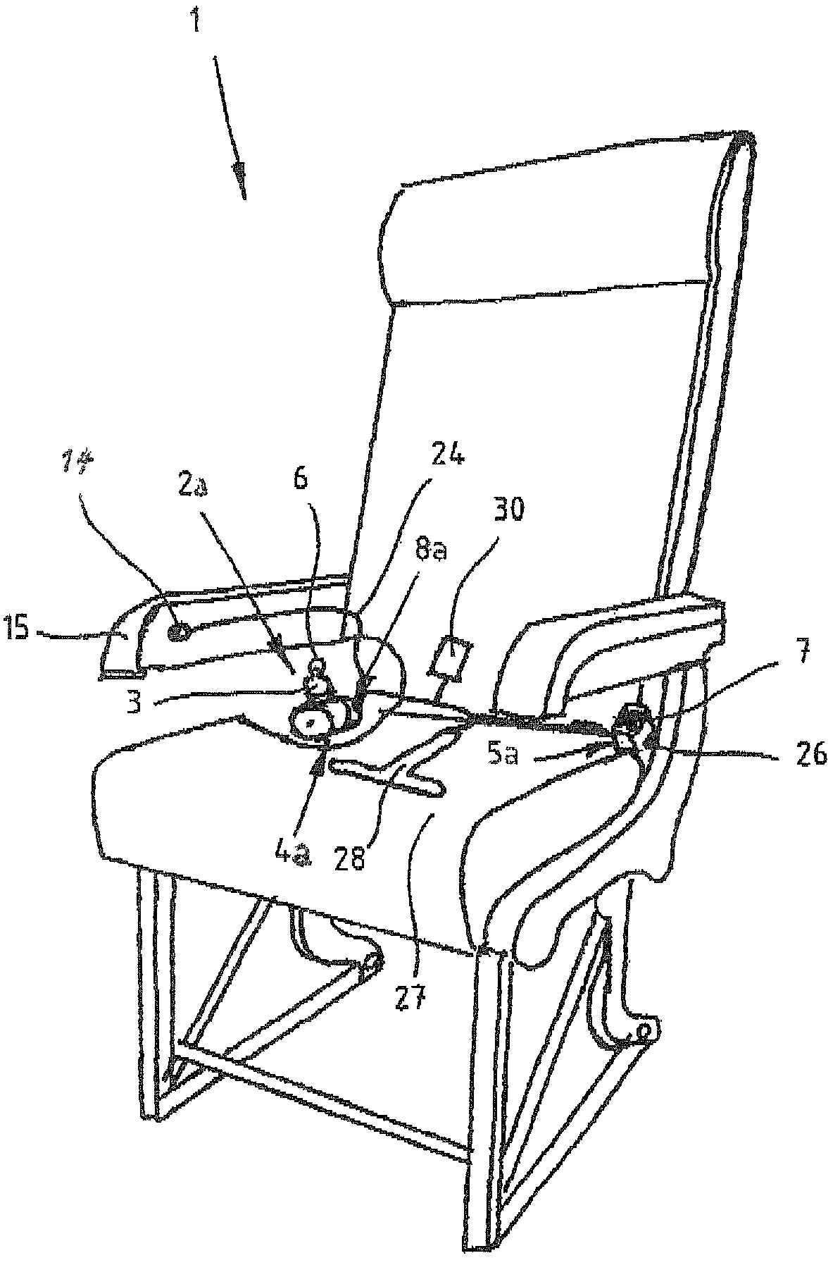
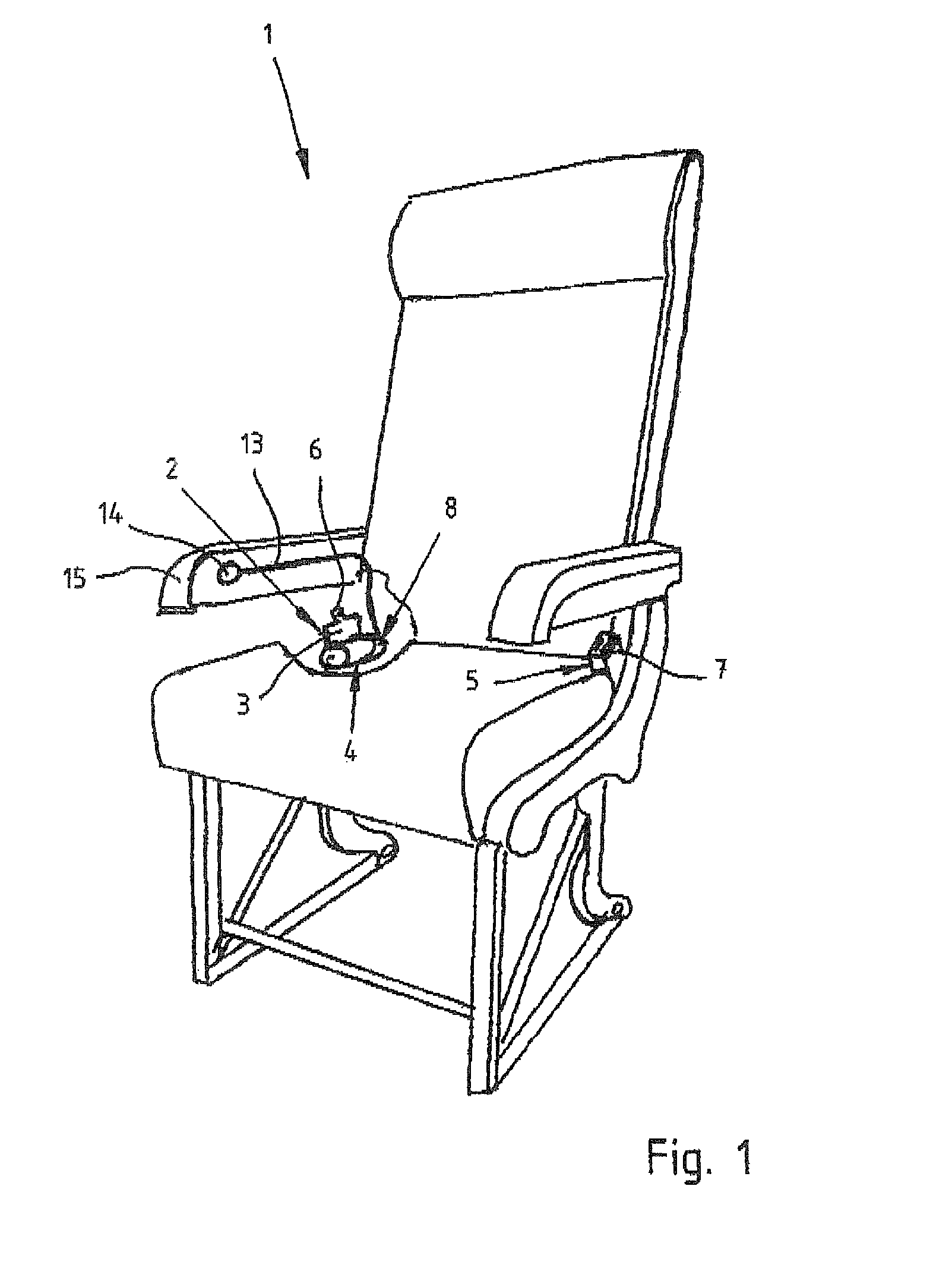
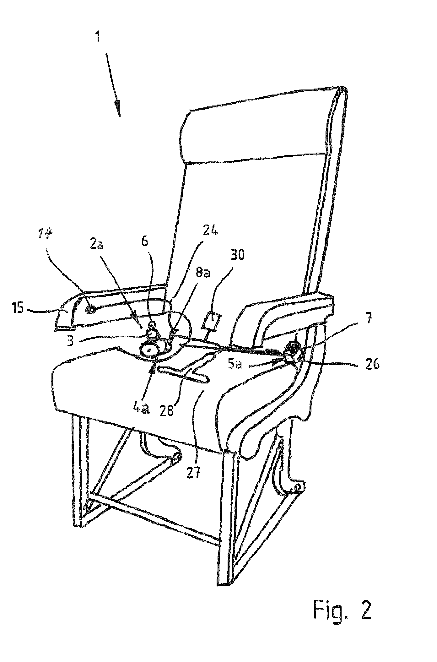
[0030]Turning now to the drawing, and in particular to FIG. 1, there is shown a perspective view of a seat, generally designated by reference numeral 1, for exemplary use in an aircraft, partially broken open and having embodied therein a safety belt according to the present invention, generally designated by reference numeral 2. The safety belt 2 is configured in the form o...


PUM


Abstract

A safety belt includes a length adjuster for securement of one end of a belt webbing, with the length adjuster being constantly biased in a direction of retraction of the belt webbing. A locking mechanism, when rendered effective, inhibits the length adjuster from turning in a direction of protraction of the belt webbing and is operatively connected to a control unit which, when activated, applies a locking function to inhibit the belt member from being pulled out of the retractor and being retracted, thereby preventing a lengthening and shortening of the belt webbing. Operatively connected to the control unit is an actuator which is constructed to allow an occupant, upon actuation, to override the locking function and thereby render the locking mechanism ineffective to enable the occupant to adjust a length of the belt webbing.

Description

BACKGROUND OF THE INVENTION[0001]The present invention relates, in general, to a safety belt, and in particular to a safety belt for use in an aircraft or military vehicles with limited space of movement.[0002]The following discussion of related art is provided to assist the reader in understanding the advantages of the invention, and is not to be construed as an admission that this related art is prior art to this invention.[0003]Safety belts for use in seats of aircrafts for example, can be designed in the form of a lap belt which, when unbuckled, automatically are pulled in. The lap belt has a belt webbing which has one end secured to a rotating length adjuster of a belt takeup and another end which has a tongue for insertion in a buckle and locking by a buckle latch in the buckle. When buckled up, the occupant is protected against potential harm in the event of turbulences. The length adjuster has a winding reel which is constantly biased in the direction of retraction of the be...

Claims


Application Information

Patent Timeline
Patent Type & Authority Patents(United States)
IPC IPC(8): B60R22/36
CPCB60R22/38B60R22/41B60R22/48B64D11/062B64D11/06B60R2022/4816B60R2022/4858B60R2022/4866B60R2022/4841
Inventor SCHUBERT, ELKERATHMANN-RAMLOW, THOMAS
Owner SCHROTH SAFETY PRODS
Learn More