
Gate assembly

a technology for gates and hinges, applied in the direction of wing fasteners, door/window fittings, building components, etc., can solve the problems of damage to the hinges of gates, and the upper hinge of gates may still sustain damag

Active Publication Date: 2011-01-25
LINDAM
View PDF11 Cites 27 Cited by
  • Summary
  • Abstract
  • Description
  • Claims
  • Application Information

AI Technical Summary

Benefits of technology

[0008]With the barrier means in the closed position, entry through the opening is substantially prevented, particularly to a small child or animal, such as a dog. With the barrier means in the open position, entry through the opening is allowable.
[0009]The provision of the tapered hinge pin recess or channel along the length thereof allows the hinge pin to undergo angular motion in use (i.e. motion through an acute angle about a substantially horizontal axis and typically in the same plane as the barrier means). Thus, the hinge means is typically capable of undergoing normal rotational movement about a substantially vertical axis or longitudinal axis of the hinge pin and, in accordance with the present invention, the hinge means can also undergo angular or tilting movement relative to the vertical or horizontal axis (i.e. rotational movement about a substantially horizontal axis or in the plane of the barrier means). The provision of movement in a number of directions accommodates any angular strain that is placed on the hinge, thus preventing damage to the hinge in use.
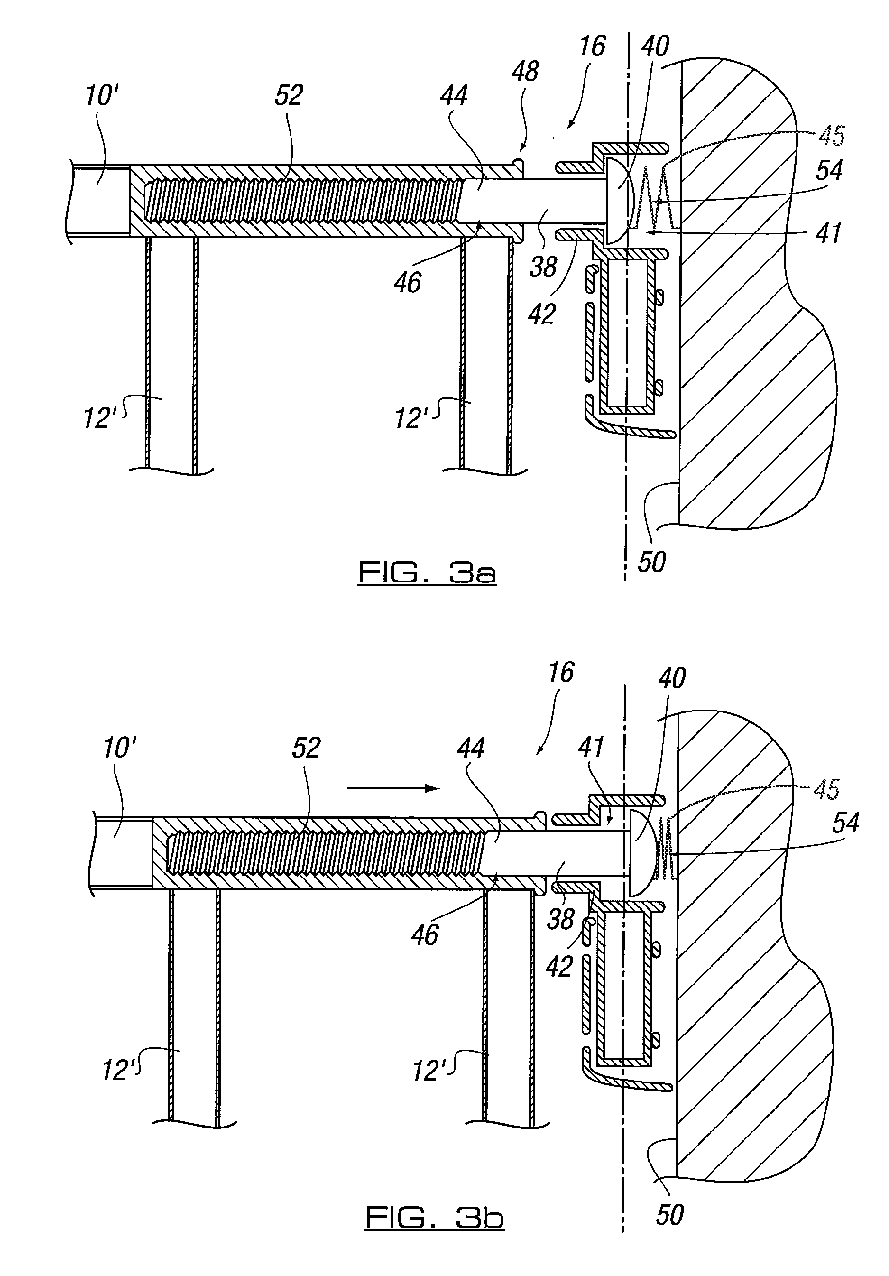
[0021]Preferably a locking element is movably mounted on or adjacent the recess opening of the keep housing. The locking element can be moved between an unlocked position, wherein the locking element is a spaced distance from the recess and the latch element can be removed from the keep housing, to a locked position, wherein the locking element is adjacent the recess opening and the latch element is substantially prevented from being removed from the keep housing.
[0028]In one embodiment said gate assembly is for positioning in an opening through which selective entry is required in use, said gate assembly including barrier means and hinge means, said method including the steps of mounting said barrier means directly or indirectly to one or more surrounding surfaces defining said opening, arranging said hinge means to allow said barrier means to be movable relative to said surrounding surfaces in use between a closed position, wherein the opening is closed, to an open position, wherein the opening is open, said hinge means including a hinge pin movably mounted in a channel or recess, and wherein the channel or recess receiving the hinge pin in use has a taper which narrows from an opening of said channel or recess through which said hinge pin is located in use towards a base or opposite end of said recess or channel, thereby allowing said barrier means to undergo angular motion relative to a substantially vertical axis during movement between said closed and open positions.

Problems solved by technology

However, a problem with such gates is that a user can accidentally apply a twisting or horizontal force in addition to the lifting force when opening the gate and this can damage the hinges of the gate since the hinges are not designed to undergo such angular movement.
However, the upper hinge on the gate may still sustain damage over time despite a degree of horizontal movement being allowed in the lower hinge.

Method used


Image

  • Gate assembly
  • Gate assembly
  • Gate assembly

Examples


Embodiment Construction

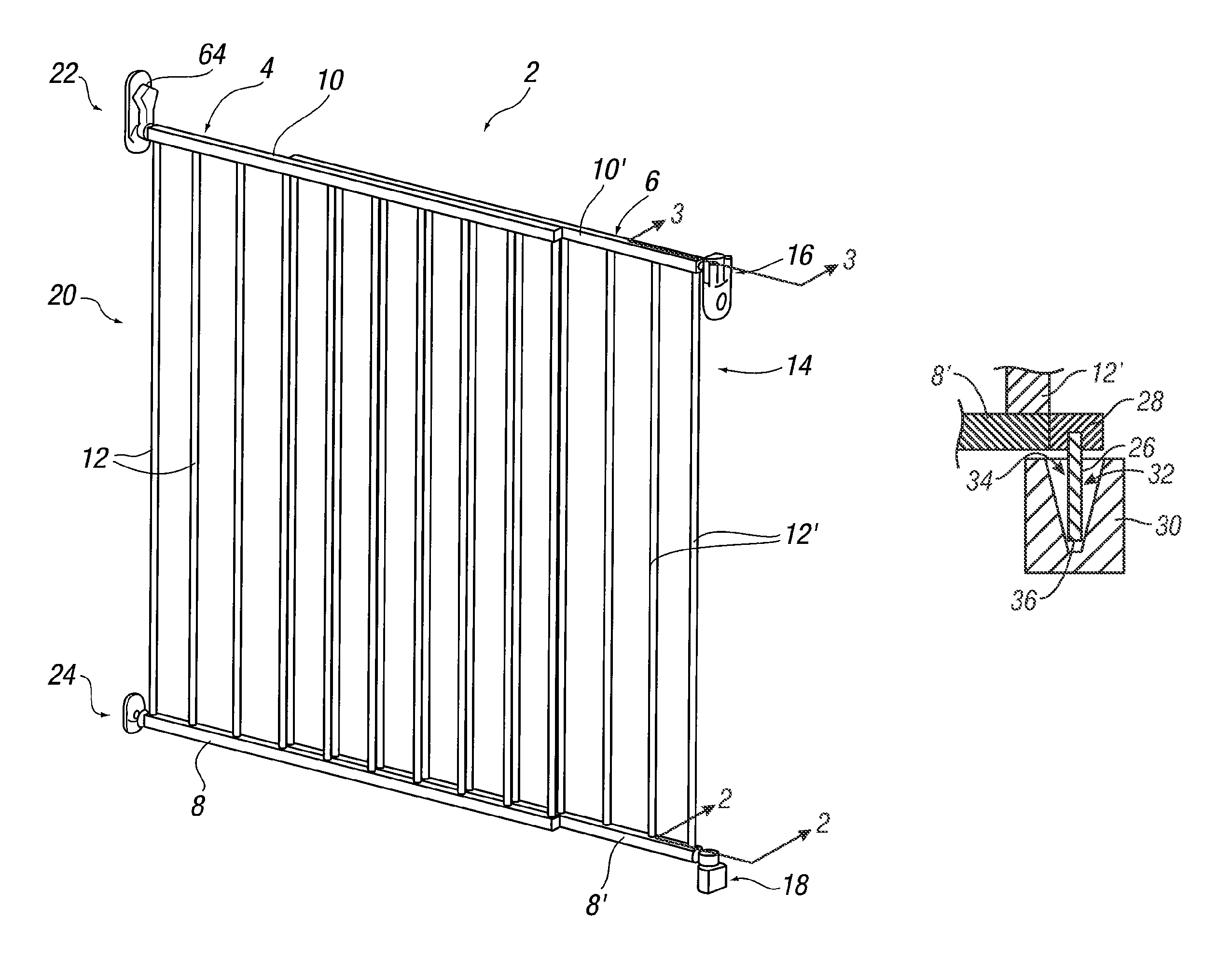
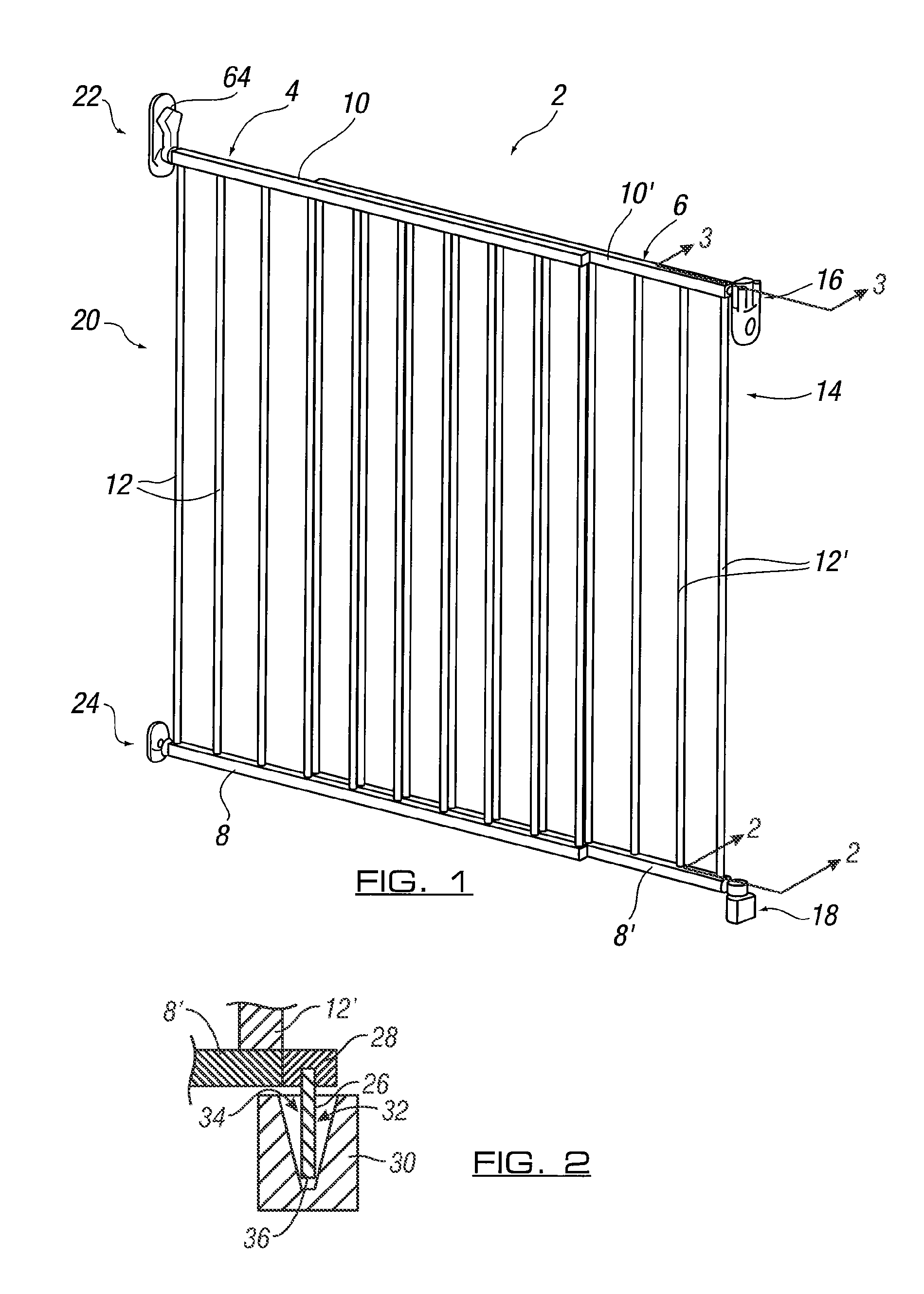
[0035]Referring firstly to FIG. 1, there is illustrated a gate assembly 2 including barrier means in the form of two gate panels 4, 6. The gate panels 4, 6 are slidably mounted to each other to allow adjustment of the width of the barrier means to allow the gate assembly to fit in different sized openings through which selective entry is required. For example, the gate assembly can be used as a child safety barrier to prevent young children or small animals from passing through the opening without adult supervision. It will be appreciated that the gate assembly of the present invention could include a single gate panel or three or more gate panels. The adjustment mechanism can be any suitable sliding or other adjustment mechanism.

[0036]Each gate panel 4, 6 includes a base member 8, 8′ and a top member 10, 10′ respectively, with a plurality of upright strut members 12, 12′ located at spaced apart intervals between the top and base members.

[0037]At one side 14 of gate panel 6 there is...


PUM


Abstract

A gate assembly is provided for positioning in an opening through which selective entry is required. The gate assembly includes barrier means mountable directly or indirectly to one or more surrounding surfaces defining the opening. Hinge means are provided to allow the barrier means to be movable relative to the surrounding surfaces in use between a closed position, wherein the opening is closed, to an open position, wherein the opening is open. The hinge means include a hinge pin movably mounted in a channel or recess. The channel or recess receiving the hinge pin in use has a taper which narrows from an opening of said channel or recess through which said hinge pin is located in use towards a base or opposite end of said recess or channel.

Description

FIELD OF THE INVENTION[0001]This invention relates to a gate assembly, and particularly but not necessarily exclusively to a gate assembly in the form of a child safety barrier or gate.BACKGROUND OF THE INVENTION[0002]It is known to provide child safety barriers which are removably located in an opening of a doorway, stairway and / or the like to prevent a child or animal from going through the opening when the barrier is fitted and in a closed position. The barriers typically include a frame which is fitted to the side walls defining the opening, and a gate or barrier which is hingedly or slidably mounted to the frame for movement between open and closed positions.[0003]In order to ensure that the child safety barriers are not accidentally opened by a young child, some conventional gates require a user to exert a substantially vertical lifting force to an upper portion of the gate prior to opening the gate. The position of where the lifting force is to be exerted on the gate is consi...

Claims


Application Information

Patent Timeline
Patent Type & Authority Patents(United States)
IPC IPC(8): E06B3/68
CPCE06B9/04E06B2009/002
Inventor YATES, ADAM
Owner LINDAM
Learn More