Microarrays for analyte detection

a microarray and analyte technology, applied in the field of microarrays for analyte detection, can solve the problems of false readings, problems such as the problem of culture and then counting, and achieve the effect of avoiding false readings

Inactive Publication Date: 2011-01-11
PURDUE RES FOUND INC
View PDF16 Cites 13 Cited by
  • Summary
  • Abstract
  • Description
  • Claims
  • Application Information

AI Technical Summary

Benefits of technology

[0013]Another preferred embodiment is useful for detecting the presence of multiple analytes having very different concentration levels in a sample. The sensor device contains a branched channel the includes a first branch having a surface that includes a plurality of microarrays containing positive array elements that target a first analyte and a second branch having a surface that includes a plurality of microarrays containing positive array elements that target a second analyte. A sample containing the first and second analytes is flowed through the branched channel such that a first amount of the sample flow enters the first branch and a second amount of the sample flow enters the second branch. For each branch the redundant pattern is then detected. This method is especially useful to detect analytes when concentration of the first analyte in the sample is at least an order of magnitude higher than the concentration of the second analyte. In that case, a larger amount sample flow is directed second branch, which contains positive array elements that target the analyte of lower concentration.

Problems solved by technology

The traditional technique, in which specimens are collected, cultured and then counted presents problems because of the long time scales usually required.
While these techniques offer promise of a reagentless detection scheme, they often suffer from false readings caused by variable flow rates, changes in pH, or fluctuations in temperature.

Method used


Image

  • Microarrays for analyte detection
  • Microarrays for analyte detection
  • Microarrays for analyte detection

Examples


examples

[0067]The present invention is illustrated by the following examples. It is to be understood that the particular examples, materials, amounts, and procedures are to be interpreted broadly in accordance with the scope and spirit of the invention as set forth herein.

example i

Redundant Patterned Protein Microarrays for Bacterial Detection

[0068]Patterned microarrays of antibodies to specific bacteria were used to perform a series of bacterial immunoassays of E. coli 0157:H7 and Renibacterium Salmoninarum (RS). Microarrays were fabricated using microcontact printing (μCP) and characterized using scanning probe microscopy (SPM). The high-resolution SPM imaging showed that bacteria had a higher binding affinity to antibody patterns than unfunctionalized regions of the substrates. Additional studies indicated a low binding affinity when bacteria were exposed to microarrays of non-specific antibodies.

Materials and Methods

[0069]Stamp fabrication. Poly(dimethylsiloxane) (PDMS) stamps were fabricated by casting and curing Sylgard 184 (Dow Corning, Midland, Mich., USA), an elastomeric polymer, against photoresist micropatterned silicone masters. The master relief pattern used to make a PDMS stamp was a negative relief of the stamp mold and was manufactured at the ...

example ii

Redundant Protein Patterning Via Microfluidic Networks

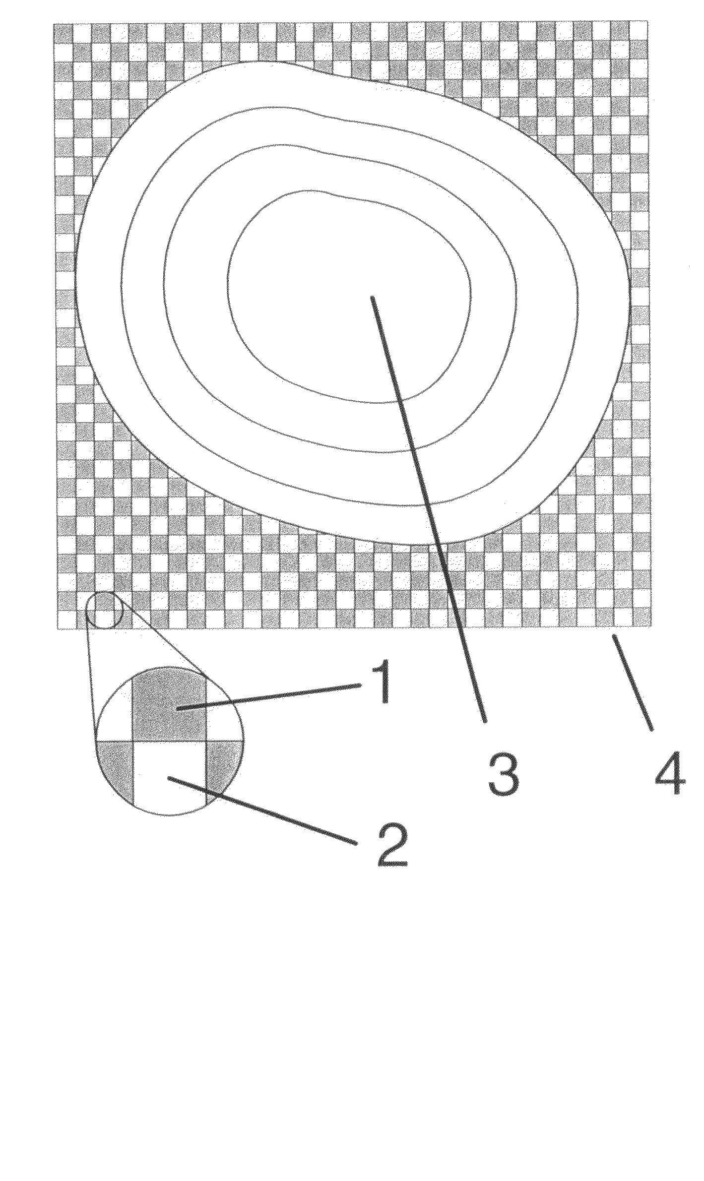
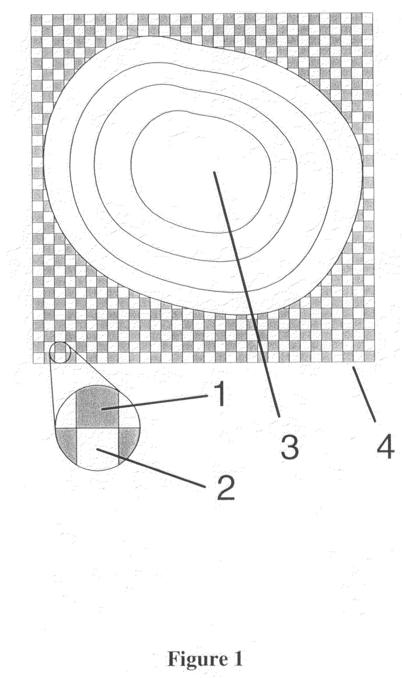
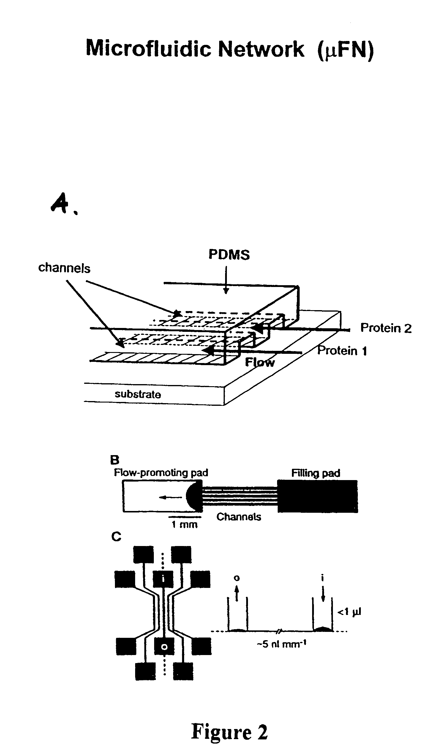
[0091]We used poly(dimethylsiloxane) (PDMS) in a microfluidic deposition network (MFN) procedure to create redundant multiple protein microarrays in a checkerboard pattern onto functionalized glass surface, thereby creating biologically active surfaces for use as immunosensors. The prototype 4-column sensor chip is shown in FIG. 9. The squares are approximately 10 μm by 10 μm, 10 μm apart, and 10 μm deep. The design of our MFN was optimized for use in a scanning probe microscope (SPM), such that multiple squares in the checkerboard pattern were visible within the maximum scan area in the microscope (about 40 μm by 40 μm). SPM and fluorescence microscopy (FM) were used to characterize the microarrays before and after performing multiple immunoassays. Additional efforts were made to minimize the adsorption of PDMS to the surface by blocking the entire PDMS MFN stamp with bovine serum albumin (BSA).

[0092]Protein microarrays fabricat...


PUM

PropertyMeasurementUnit
volumeaaaaaaaaaa
scan sizeaaaaaaaaaa
scan sizeaaaaaaaaaa

Abstract

Method and device for detection of analytes, particularly biohazards. A microarray containing immobilized sensing molecules captures complementary analytes on a redundant patterned substrate. Pattern analysis is performed using a computer algorithm.

Description

[0001]This application claims the benefit of U.S. Provisional Application Ser. No. 60 / 400,225, filed 1 Aug. 2002, which is incorporated herein by reference in its entirety.STATEMENT OF GOVERNMENT RIGHTS[0002]This invention was made with government support under a grant from the United States Navy, Grant No. N00164-00-C-0047. The U.S. Government has certain rights in this invention.BACKGROUND OF THE INVENTION[0003]Recent events have triggered a strong interest in sensitive detection of viruses and bacteria. Various strategies have been proposed to detect the presence of bacterial contaminants. The traditional technique, in which specimens are collected, cultured and then counted presents problems because of the long time scales usually required. To solve this problem, indirect techniques have been proposed in which the presence of bacteria is rapidly inferred from changes in a transducer output signal. These indirect techniques include electrochemical methods and quartz microbalance ...

Claims


Application Information

Patent Timeline
Patent Type & Authority Patents(United States)
IPC IPC(8): C12M1/34C12M3/00
CPCG01N27/3276
Inventor REGNIER, FRED E.REIFENBERGER, RONALD GEORGEINEROWICZ, HALINA DOROTAHOWELL, STEPHEN WAYNE
Owner PURDUE RES FOUND INC
Why Eureka
Try Eureka