Dry running flexible impeller pump and method of manufacture

a technology of flexible impeller and impeller blade, which is applied in the direction of liquid fuel engines, vessel construction, marine propulsion, etc., can solve the problems of no acceptable prior art dry running flexible impeller pumps, impeller blades or vanes may wear flat, and the bead of impeller blades or vanes may not be able to meet the requirements of use, so as to reduce friction

Inactive Publication Date: 2011-01-11
HARVIE MARK R
View PDF6 Cites 20 Cited by
  • Summary
  • Abstract
  • Description
  • Claims
  • Application Information

AI Technical Summary

Problems solved by technology

A review of prior and current flexible impeller pump technologies reveal that there are no acceptable prior art Dry Running Flexible Impeller Pumps that permit a flexible impeller pump to be run dry, even for a very few seconds, without certain catastrophic failure of the pump in general and specifically the impeller.
It is these precise situations where a user, perhaps distracted by something else, leaves the impeller pump on to do its job emptying a vessel or fluid repository and then forgets that it has been left running, then the fluid runs dry, the pump housing runs dry and the friction of the impeller against the cam of the pump housing causes an almost immediate failure of the impeller.
The bead of the impeller blades or vanes may wear flat.
Each of these in essence lead to the same result, the pump no longer works.
Therein, lies the problem with current and prior art flexible impeller pumps.
Since the pump requires the fluid being pumped to be present in order to remain lubricated, once the pump runs dry the friction of the impeller against the cam portion of the pump housing will cause permanent damage to the impeller within no more than 15 to 20 seconds of dry running operation.
In practice, however, these prior art patents teach a pump technology wherein the rotation speed of the impeller increases, fluid will begin to pass between the impeller and the housing wall limiting the effective speed and maximum operating pressure of the pump.
The inner surface of the bore on which each plate rotates is especially subject to wear especially if the pump is run dry.
Despite its improvement over E. C. Rumsey in U.S. Pat. No. 2,455,194, Takahashi in U.S. Pat. No. 3,832,105, and McCormick in U.S. Pat. No. 4,940,402, Maki also fails to teach a flexible impeller pump that may be run dry for any more than just a few seconds without permanently damaging the impeller and / or the pump.
While each of these prior art flexible impeller pump devices fulfill their respective particular objectives and requirements, and are most likely quite functional for their intended purposes, it will be noticed that none of the prior art cited disclose an apparatus and / or method of manufacture that is capable of being run dry for extended periods of time without pump failure.

Method used


Image

  • Dry running flexible impeller pump and method of manufacture
  • Dry running flexible impeller pump and method of manufacture
  • Dry running flexible impeller pump and method of manufacture

Examples


Embodiment Construction

I. Preferred Embodiments

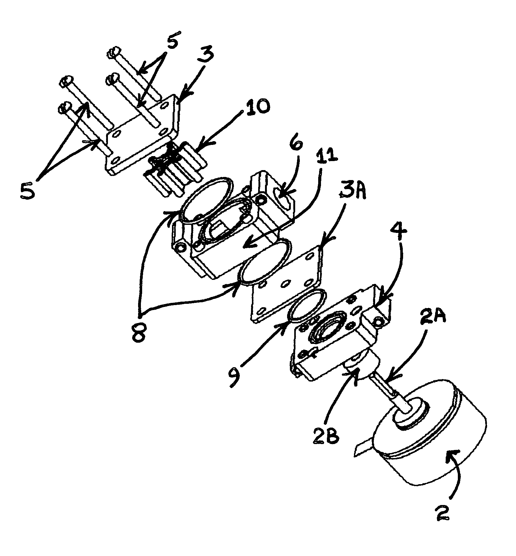
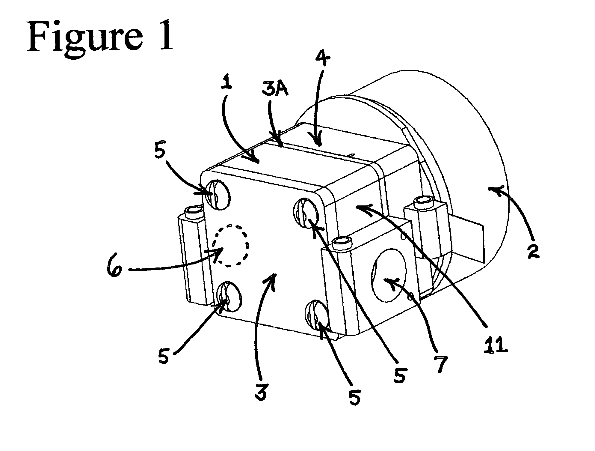
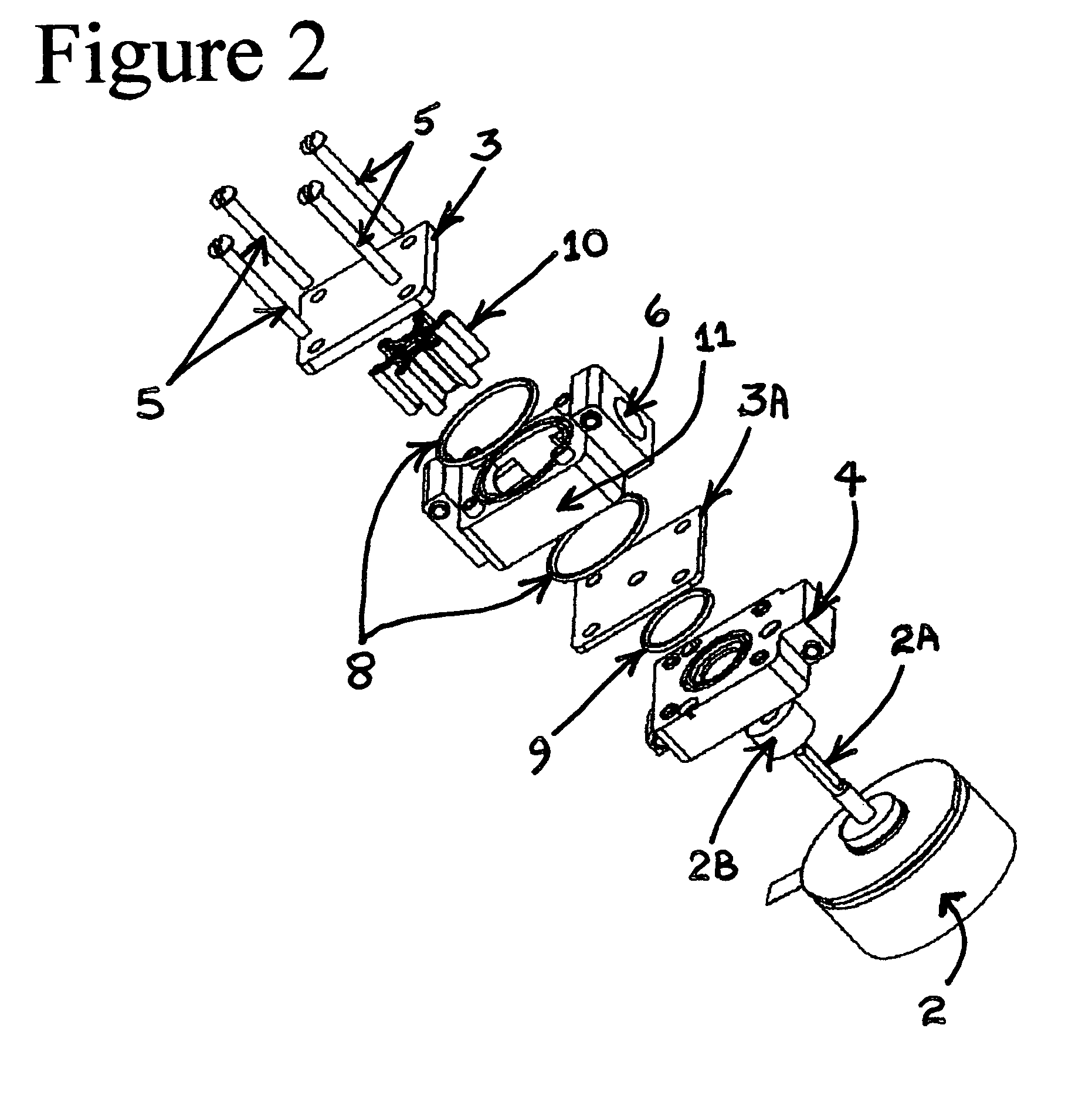
[0024]With reference now to the drawings, and in particular to FIGS. 1-2 thereof, a new and novel Dry Running Flexible Impeller Pump device embodying the principles and concepts of the present invention is depicted in these drawings as comprising five major components: 1) a Flexible Impeller (10) sandwiched between; 2) two End Plates (3) mounted to; 3) a Pump Housing (11) to which is attached; 4) a Drive Motor Mount (4) to which is attached; 5) a Drive Motor (2) the Drive Motor Shaft (2A) of which is keyed into the Flexible Impeller (10) to rotate the Flexible Impeller (10) within the Pump Housing (11) and between the two End Plates (3), and the Dry Running Flexible Impeller Pump is generally designated by the reference numeral (1).

General Description of Reference Numerals in the Description and Drawings

[0025]Any actual dimensions listed are those of the preferred embodiment. Actual dimensions or exact hardware details and means may vary in a final product or...


PUM


Abstract

This invention relates to a Dry Running Flexible Impeller Pump and Method of Manufacture that is specifically designed to provide a flexible impeller pump that is capable of being run dry for extended periods of time without damaging the impeller. The pump's housing and end plates are coated with a low friction industrial coating to limit the heat of friction created by the flexible impeller while in use. Additionally the flexible impeller is cast from a pre-molding silicone substrate that contains no mold release and is cast in a mold that is treated with a low friction industrial coating and is cast without mold release. Once the flexible impeller is removed from the mold it is cleaned with alcohol, baked in a vacuum at a temperature of at least 100° C., and then coated with a Paralene N coating by vacuum deposition.

Description

BACKGROUND ART[0001]A review of prior and current flexible impeller pump technologies reveal that there are no acceptable prior art Dry Running Flexible Impeller Pumps that permit a flexible impeller pump to be run dry, even for a very few seconds, without certain catastrophic failure of the pump in general and specifically the impeller. Ironically, the very applications for which flexible impeller pumps are especially suited, are generally those types of situations where a finite source of fluids are sought to be disposed of completely where the pumping process is intended to completely pump all fluid present. It is these precise situations where a user, perhaps distracted by something else, leaves the impeller pump on to do its job emptying a vessel or fluid repository and then forgets that it has been left running, then the fluid runs dry, the pump housing runs dry and the friction of the impeller against the cam of the pump housing causes an almost immediate failure of the impel...

Claims


Application Information

Patent Timeline
Patent Type & Authority Patents(United States)
IPC IPC(8): F04C5/00F01D5/02
CPCF04C5/00F04C2230/20F04C2230/21F05C2225/00
Inventor HARVIE, MARK R.
Owner HARVIE MARK R
Why Eureka
Try Eureka