
Power utility connector with a plurality of conductor receiving channels

a technology of power utility connectors and receiving channels, which is applied in the field of electric connectors, can solve the problems of increasing the overall cost of the bolt-on connector system, more difficult installation, and poor installation, and achieve the effect of reducing costs

Inactive Publication Date: 2011-01-04
TE CONNECTIVITY CORP
View PDF37 Cites 36 Cited by
  • Summary
  • Abstract
  • Description
  • Claims
  • Application Information

AI Technical Summary

Benefits of technology

The patent text describes an electrical connector assembly for power utility transmission conductors. The assembly includes two separate conductive members that are joined together to capture the main and tap power line conductors. The main and tap conductive members have separate channels that are designed to receive different sized conductors. The assembly can be easily joined together using a fastener. The technical effect of this invention is to provide a reliable and flexible connection for power transmission that can adapt to different needs and situations.

Problems solved by technology

Such bolt-on connectors have been widely accepted in the industry primarily due to their ease of installation, but such connectors are not without disadvantages.
Due to the limited range taking ability of known bolt-on connectors, the part count needed is increased, which increases the overall cost of the bolt-on connector system.
Such compression connectors are generally available at a lower cost than bolt-on connectors, but are more difficult to install.
Poorly installed or improperly installed compression connectors can present reliability issues in power distribution systems.
As a result, AMPACT connectors tend to be expensive due to the increased part count.
The increased part count increases the overall expense and complexity of the AMPACT connectors.

Method used


Image

  • Power utility connector with a plurality of conductor receiving channels
  • Power utility connector with a plurality of conductor receiving channels
  • Power utility connector with a plurality of conductor receiving channels

Examples


Embodiment Construction

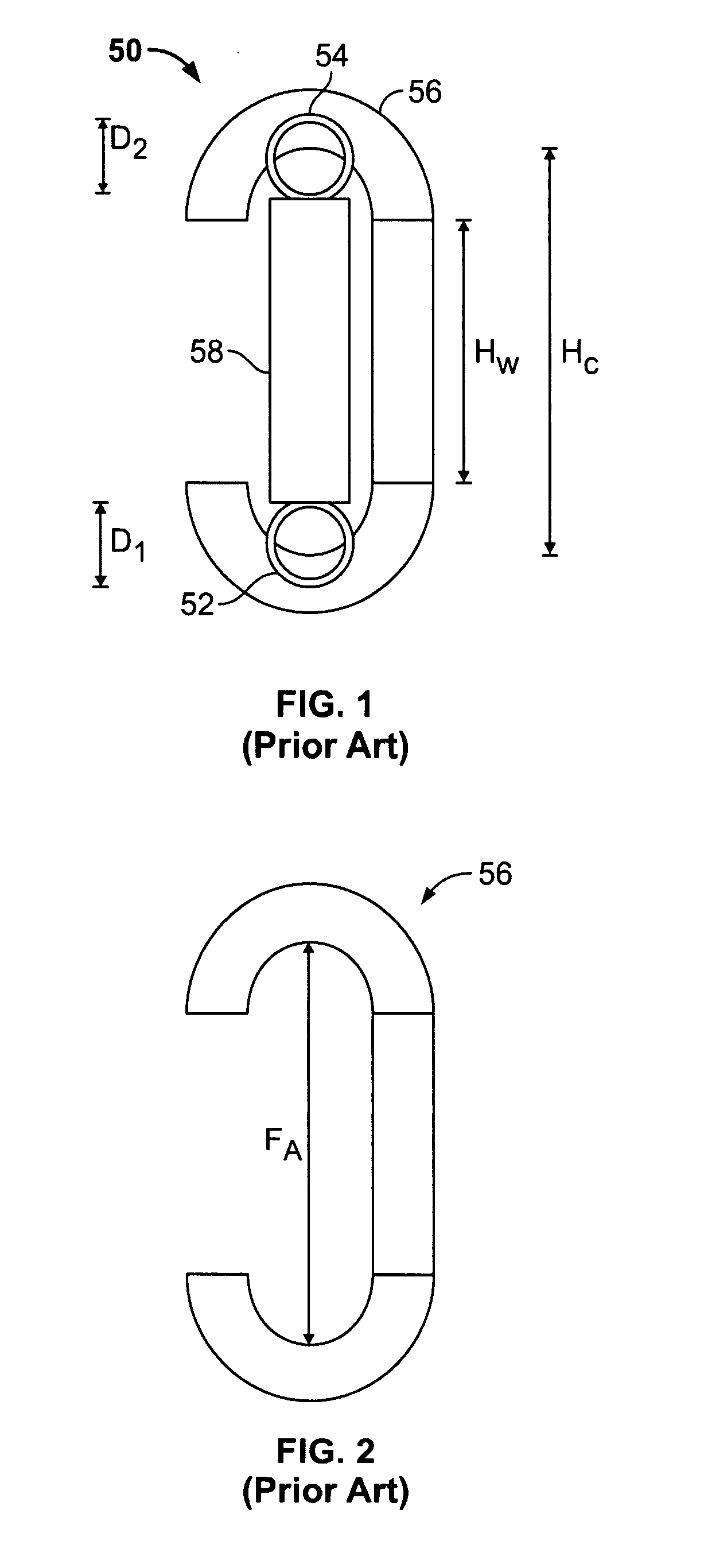
[0020]FIGS. 1 and 2 illustrate a known wedge connector assembly 50 for power utility applications wherein mechanical and electrical connections between a tap or distribution conductor 52 and a main power conductor 54 are to be established. The connector assembly 50 includes a C-shaped spring member 56 and a wedge member 58. The spring member 56 hooks over the main power conductor 54 and the tap conductor 52, and the wedge member 58 is driven through the spring member 56 to clamp the conductors 52, 54 between the ends of the wedge member 58 and the ends of the spring member 56.

[0021]The wedge member 58 may be installed with special tooling having for example, gunpowder packed cartridges, and as the wedge member 58 is forced into the spring member 56, the ends of the spring member 56 are deflected outwardly and away from one another via the applied force FA shown in FIG. 2. Typically, the wedge member 58 is fully driven to a final position wherein the rear end of the wedge member 58 i...


PUM


Abstract

An electrical connector assembly includes a main conductive member and a tap conductive member separately fabricated from one another. Each of the main and tap conductive members including at least one conductor receiving channel, wherein the main and tap conductive members together include at least three channels configured to receive conductors therein and extending along three different channel axes. The channel(s) of the main conductive member is configured to receive a main power line conductor, and the channel(s) of the tap conductive member is configured to receive a tap power line conductor. The main and tap conductive members are joined to one another such that the main conductive member and the tap conductive member cooperate to capture the main power line conductor therebetween when the main and tap conductive members are joined, and the tap conductive member and the main conductive member cooperate to capture the tap power line conductor therebetween when the main and tap conductive members are joined.

Description

BACKGROUND OF THE INVENTION[0001]This invention relates generally to electrical connectors, and more particularly, to power utility connectors for mechanically and electrically connecting a tap or distribution conductor to a main electrical transmission conductor.[0002]Electrical utility firms constructing, operating and maintaining overhead and / or underground power distribution networks and systems utilize connectors to tap main power transmission conductors and feed electrical power to distribution line conductors, sometimes referred to as tap conductors. The main power line conductors and the tap conductors are typically high voltage cables that are relatively large in diameter, and the main power line conductor may be differently sized from the tap conductor, requiring specially designed connector components to adequately connect tap conductors to main power line conductors. Generally speaking, three types of connectors are commonly used for such purposes, namely bolt-on connect...

Claims


Application Information

Patent Timeline
Patent Type & Authority Patents(United States)
IPC IPC(8): H01R11/01
CPCH01R4/5091
Inventor COPPER, CHARLES DUDLEY
Owner TE CONNECTIVITY CORP
Learn More