
Wearing-type motion assistance device and program for control

a technology of motion assistance and wearable devices, which is applied in the field of wearable action assistance devices and its control, can solve the problems of physical handicap, difficulty for elderly people with muscle strength decline or physical handicap, and achieve the effect of sufficient conformity, avoiding poor sensitivity or oversensitivity, and sufficient conformity

Active Publication Date: 2010-12-28
CYBERDYNE INC
View PDF21 Cites 44 Cited by
  • Summary
  • Abstract
  • Description
  • Claims
  • Application Information

AI Technical Summary

Benefits of technology

[0022]According to embodiments of the wearable action-assist device of the invention, in the state where a wearer wears the action-assist device, the kinetics parameters intrinsic to the wearer concerned are identified by a parameter identification unit. And the drive source can be controlled by the control unit based on the equation of motion into which the identified kinetics parameters are substituted. It is possible to demonstrate sufficient effect in conformity with the control method used by the control unit, without being influenced by the change factors, such as wearer's individual difference and physical condition.
[0023]Moreover, according to the embodiments of the invention, the drive source can be controlled by the control unit based on the equation of motion into which the muscle torque or muscle force estimated by the muscle torque estimation unit is further substituted. The kinetics parameters can be identified even in the state where a muscle force is produced by the wearer, and the above-mentioned effect can be demonstrated without taking the latency time for identifying the kinetics parameters.
[0024]Moreover, according to the embodiments of the invention, the wearable action-assist device further comprises a calibration unit adjusting a gain between a biosignal detected by the biosignal detection unit and a muscle torque or muscle force estimated by the muscle torque estimation unit, so that an association between the biosignal and the muscle torque or muscle force is in conformity with a predetermined association. It is possible to avoid the occurrence of poor sensitivity or oversensitivity due to the detection result received from the biosignal detection unit. As a result, it is possible to avoid the situation where the identification accuracy of the kinetics parameters of the wearer falls, and it is possible to avoid the situation where the assisting force generated by the drive source becomes too small or too large.
[0025]Moreover, according to the embodiments of the invention, the control unit is configured to control the drive source according to a control method using the kinetics parameters identified by the parameter identification unit and performing at least one of gravity compensation and inertia compensation. It is possible to suppress the situation where the weight of the action-assist device gives the wearer sense of burden, and the situation where the inertia of the action-assist device gives the wearer sense of incongruity at the time of operation.
[0026]Moreover, according to the embodiments of the invention, the control unit is configured to control the drive source according to an impedance control method using the kinetics parameters identified by the parameter identification unit. It is possible to demonstrate sufficient effect in conformity with the impedance control method in which the apparent inertia, the apparent viscosity, etc. of the action-assist device are reduced so as to realize light operation.

Problems solved by technology

In many cases, it is difficult for elderly people having muscle strength decline or physically handicapped people having lost muscle strength to perform an action or operation that can easily be performed by a healthy person.

Method used


Image

  • Wearing-type motion assistance device and program for control
  • Wearing-type motion assistance device and program for control
  • Wearing-type motion assistance device and program for control

Examples


embodiments

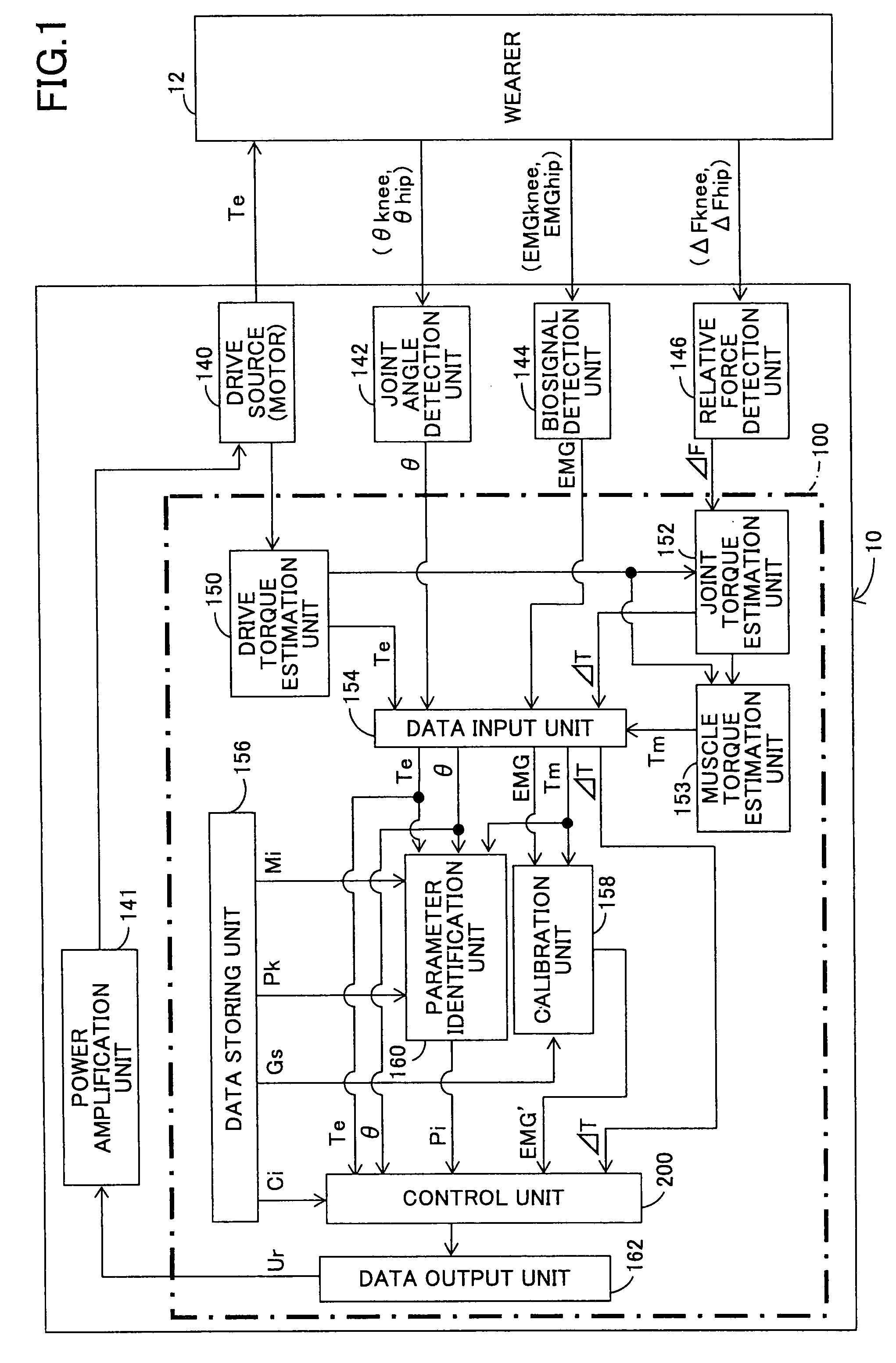
[0094]FIG. 1 shows the composition of a control system of a wearable action-assist device in an embodiment of the invention.

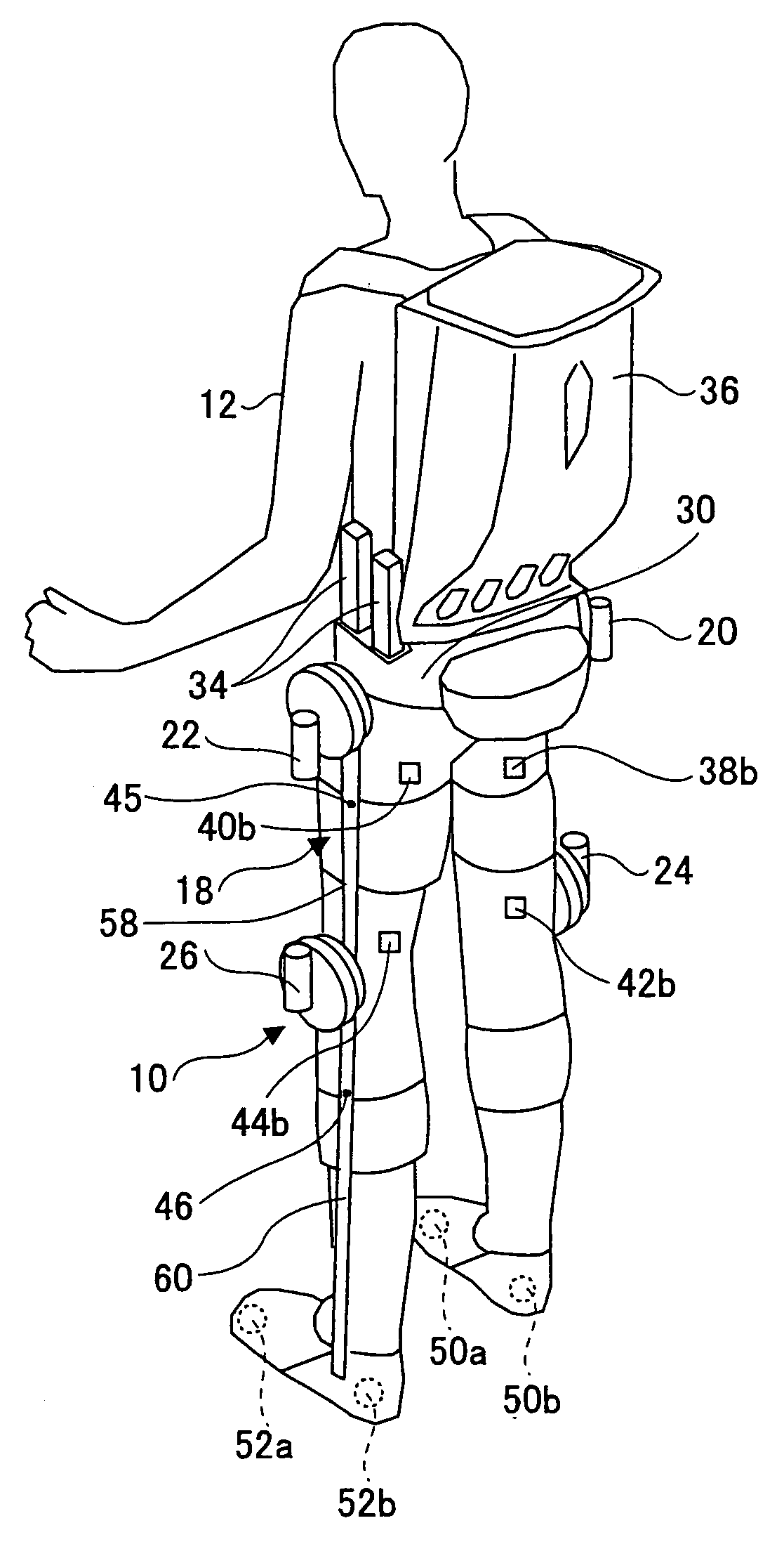
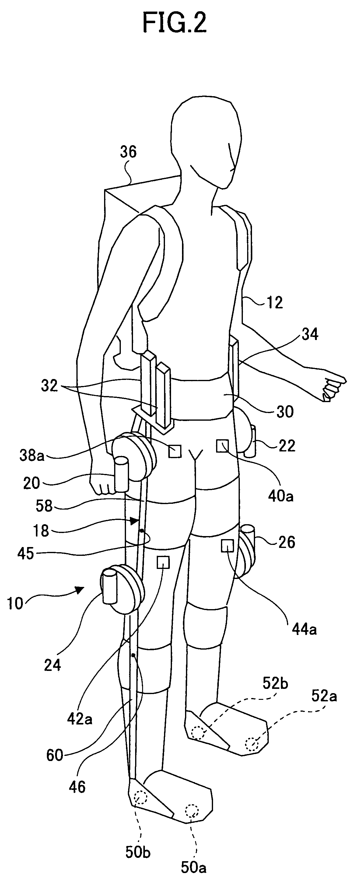
[0095]As shown in FIG. 1, the wearable action-assist device 10 includes a drive source 140 which supplies an assisting force to a the wearer 12, a joint angle detection unit 142 which detects an angular displacement θ of each joint of the wearer 12, a biosignal detection unit 144 which detects a myoelectricity signal (biosignal) according to the muscle force generated by the wearer 12, and a relative force detection unit 146 which detects a relative force (ΔF) acting on the action-assist device 10.

[0096]This assisting force is to create the torque acting on the wearer around each joint of an action-assist wearing tool 18 shown in FIG. 2 and FIG. 3 (equivalent to each of knee joints and a hip joint of the wearer 12) as the axis of rotation. The assisting force may also be mentioned as assisting torque.

[0097]The relative force detection unit 146 detects the relat...


PUM


Abstract

A motion assistance device has a biological signal detection means for detecting a biological signal from the wearer of the device; a motion assistance device installation member having a drive source for applying torque acting to the wearer by use of each joint of the wearer as a rotating shaft; a control means for controlling the drive source to generate torque corresponding to the biological signal detected by the biological signal detection mean; a drive torque estimation means for estimating the drive torque generated by the drive source; a joint angle detection means for detecting angular displacement of a joint; and a parameter identification means for substituting the drive torque estimated by the drive torque estimation means and the angular displacement detected by the joint angle detection means into an equation of motion to specify the wearer-specific dynamics parameter, the equation relating to the entire system and including wearer-specific dynamics parameter. The control means controls the drive source according to a predetermined control method, based on the equation of motion into which the dynamics parameter identified by the parameter identification means is substituted.

Description

TECHNICAL FIELD[0001]This invention relates to a wearable action-assist device, and more particularly to improvement of a wearable action-assist device and its control program in which an action of a wearer is assisted or executed by substituting for the wearer.BACKGROUND ART[0002]In many cases, it is difficult for elderly people having muscle strength decline or physically handicapped people having lost muscle strength to perform an action or operation that can easily be performed by a healthy person. For this reason, development of various power assist devices is now in progress in order to assist or execute action of these people by substituting for them.[0003]Among these power assist devices, there is a wearable action-assist device (which is also called action-assist device) which is put on a user (which is also called wearer), for example. Typically, the power-assist device of this kind includes a myoelectricity sensor (biosignal detection unit) which detects a myoelectricity ...

Claims


Application Information

Patent Timeline
Patent Type & Authority Patents(United States)
IPC IPC(8): A61H1/00
CPCA61H3/008B25J9/0006A61H1/0255A61H3/00A61H2230/605A61H2201/018A61H2201/165A61H2201/5069A61H2230/60A61H2201/1614A61H2201/1628A61H2201/1642A61H2201/1676A61H2201/5061A61H2201/0176A61F2/72G05B13/02A61B5/24A63B23/04A63B24/0087
Inventor SANKAI, YOSHIYUKI
Owner CYBERDYNE INC
Learn More