
Golf club

a technology for golf clubs and swings, applied in golf clubs, racket sports, sport apparatus, etc., can solve the problems of difficult to master a proper swing path and the rotation of the ball, and achieve the effect of increasing the range in which the swing balance changes, increasing the effectiveness of shifting, and increasing the rang

Inactive Publication Date: 2010-12-28
BEPPU KAZUMASA
View PDF11 Cites 18 Cited by
  • Summary
  • Abstract
  • Description
  • Claims
  • Application Information

AI Technical Summary

Benefits of technology

[0011]By the way, a practice exercised most enthusiastically by general amateur golfers is to actually hit balls in a golf driving range, since they can take the joy of actually hitting the balls and check how the balls fly. Therefore, a practice which will allow golfers to easily master a proper swing path while they can actually hit balls in the driving range will provide the general amateur golfers with a meaningful method of practice.
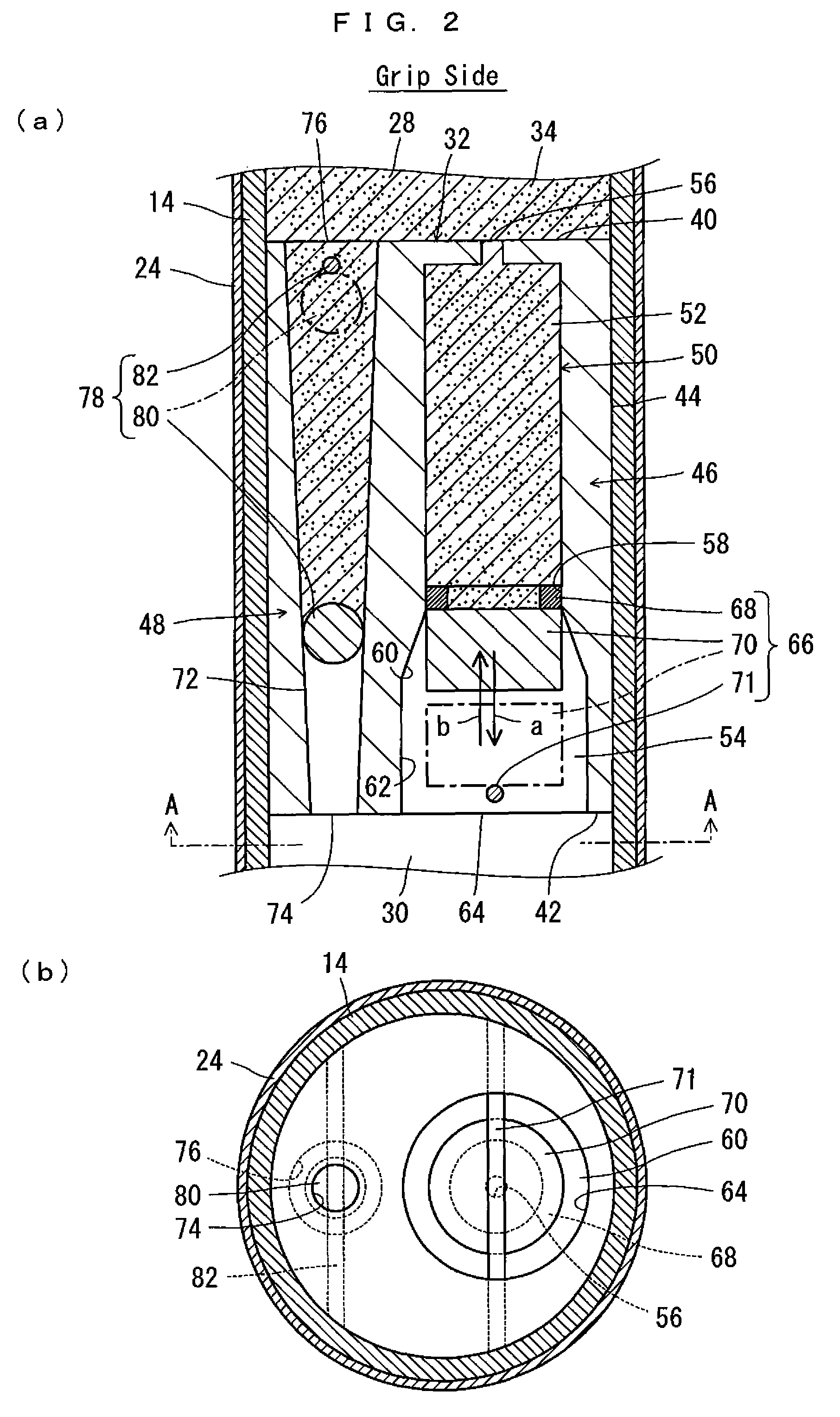
[0021]Further preferably, the second shifter portion includes a second communication portion for providing communication between the second portion and the first portion for moving the balancing material from the second portion side to the first portion; and a second valve mechanism capable of opening and closing the second communication portion. With this arrangement, the second valve mechanism uses its weight to open the second communication portion. In this case, when returning the balancing material which was shifted to the second portion side to the first portion, it is only required to keep the golf club in a certain attitude, i.e., with the club head on the upside and the grip on the downside, and then the second valve mechanism will open the second communication portion using the weight of the mechanism itself. Thus, the balancing material on the second portion side moves due to its weight, through the second communication portion toward the first portion, and decreases the swing balance. Therefore, there is no need for a dedicated drive-power source (such as a motor) in order to return the balancing material to the first portion, and it is possible to simplify the structure of the golf club.

Problems solved by technology

However, since the golfer cannot see his swing path by himself, it is not easy to master a proper swing path.
Especially, there is a major tendency in many beginners that their swing often causes the ball to make slice rotation.

Method used


Image

  • Golf club
  • Golf club
  • Golf club

Examples


Embodiment Construction

[0031]Hereinafter, embodiments of the present invention will be described with reference to the drawings.

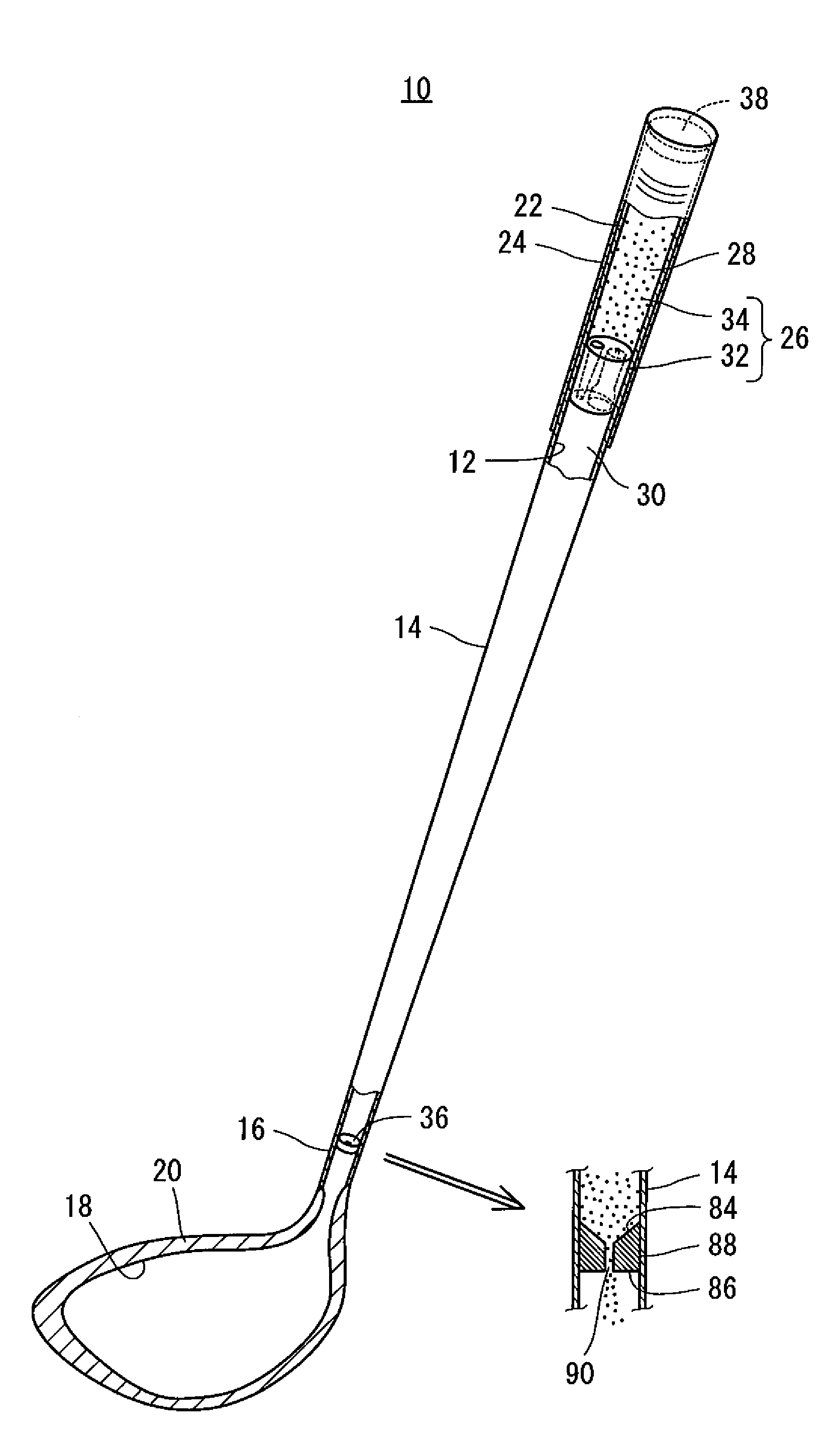
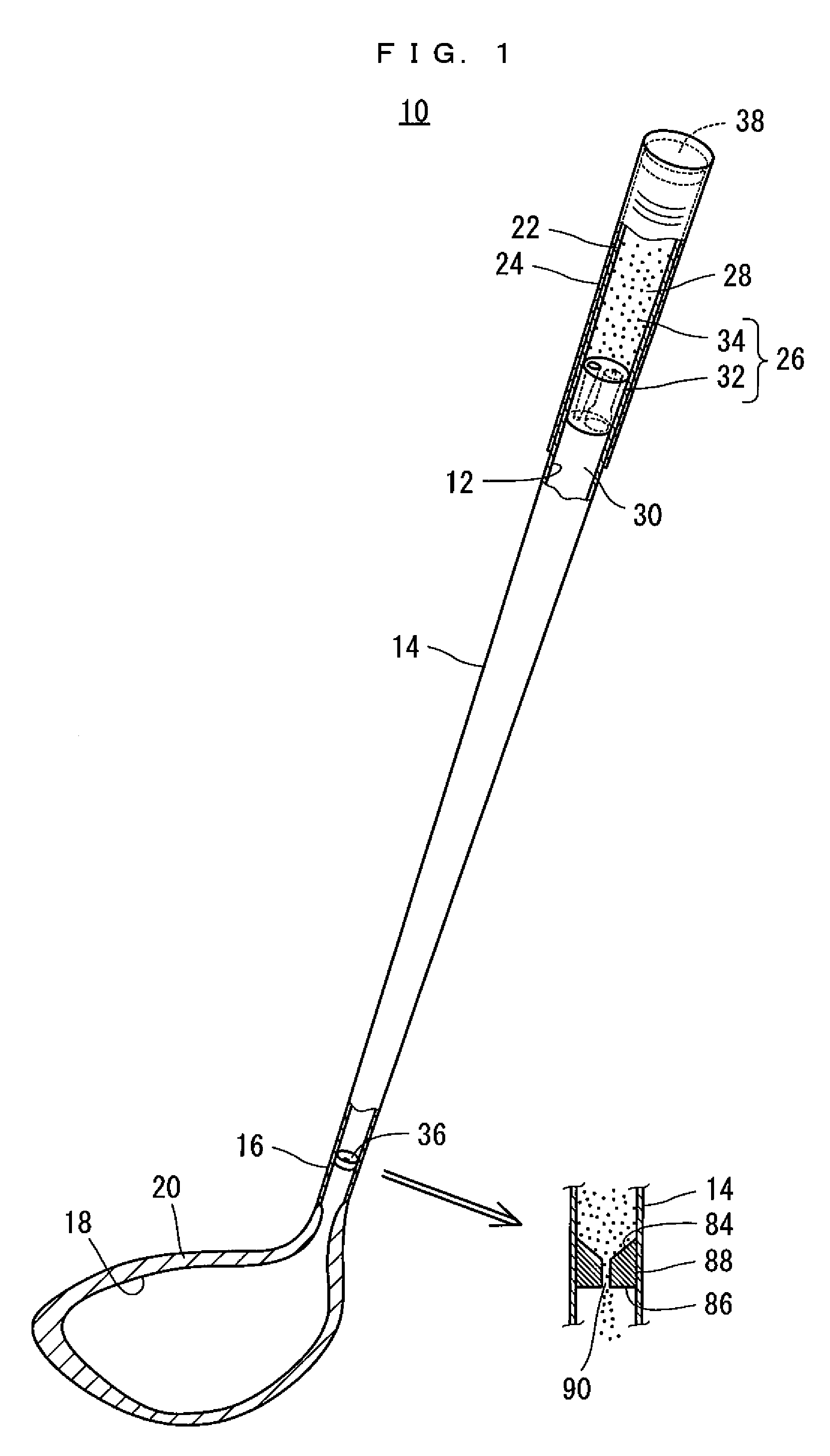
[0032]Referring to FIG. 1, a golf club 10 according to an embodiment of the present invention is a practice golf club, and includes a shaft 14 which has a hollow portion 12; an wood-type club head 20 which is provided at a tip portion 16 of the shaft 14 and has a hollow portion 18; and a grip 24 which is provided at a base end portion 22 of the shaft 14. The shaft 14 is made of steel or carbon for example, and has a total length of 44.5 inches. The shaft 14, the club head 20 and the grip 24 may each be provided by commercially available golf club parts. The golf club 10 has nothing that would look differently from a commercially available normal golf driver, but incorporates therein balance-shifting means 26. The balance-shifting means 26 includes a partitioning portion 32 which divides the hollow portion 12 in the shaft 14 into a first portion 28 on the base end portion 22 side ...


PUM


Abstract

A golf club which helps master a proper swing path is provided. A golf club includes a hollow shaft; a club head at a tip portion of the shaft; a grip at a base end portion of the shaft; and a balance-shifting unit which increases a swing balance of the golf club. The balance-shifting unit includes a partitioning portion which divides an inside space of the shaft into a first portion on the base end portion side and a second portion on the tip portion side; and a balancing material. The partitioning portion includes a first shifter portion which allows the balancing material held in the first portion to move to the second portion side in association with a swing; and a second shifter portion which allows the balancing material on the second portion side to return to the first portion. The golf club further includes a balance holder.

Description

FIELD OF THE INVENTION[0001]The present invention relates to a golf club, and more specifically to a practice golf club for mastering a proper swing path.BACKGROUND ART[0002]A golf swing is composed of a sequence of swing actions starting from an address, a back swing, a top swing, a down swing which leads to an impact and then through a follow-through, coming to a finish. During this series of swing actions from address to finish, the club head moves in a circular path. By making a swing so that the lowest point of the circular path is the ball position, it becomes possible to drive the ball accurately toward a target. A plane which contains the circular path made by the club head when such a swing is made is called swing plane. If the club head travels out of the swing plane during the swing, the ball is likely to make slice rotation or hook rotation.[0003]Therefore, in order to stabilize shots, it is necessary to master a proper swing path along the swing plane. However, since th...

Claims


Application Information

Patent Timeline
Patent Type & Authority Patents(United States)
IPC IPC(8): A63B69/36
CPCA63B53/00A63B53/08A63B69/3632A63B59/0074A63B59/0088A63B53/0466A63B2053/0495A63B2059/0081A63B69/3611A63B60/42A63B60/50A63B69/36A63B60/0081A63B60/00
Inventor BEPPU, KAZUMASA
Owner BEPPU KAZUMASA
Learn More