Eureka AIR delivers breakthrough ideas for toughest innovation challenges, trusted by R&D personnel around the world.

Engine inlet deep acoustic liner section

a technology for acoustic liner section and engine inlet, which is applied in the direction of machines/engines, liquid fuel engines, transportation and packaging, etc., can solve the problem of insufficient acoustic panels in the prior ar

Active Publication Date: 2010-12-28
ROLLS ROYCE DEUT LTD & CO KG
View PDF16 Cites 38 Cited by
  • Summary
  • Abstract
  • Description
  • Claims
  • Application Information

AI Technical Summary

Problems solved by technology

However, prior art acoustic panels are insufficient under certain conditions for reducing fan flutter cause by certain engine fan harmonics.

Method used


Image

  • Engine inlet deep acoustic liner section
  • Engine inlet deep acoustic liner section
  • Engine inlet deep acoustic liner section

Examples


Embodiment Construction

[0019]The following detailed description of the invention references the accompanying drawings that illustrate specific embodiments in which the invention can be practiced. The embodiments are intended to describe aspects of the invention in sufficient detail to enable those skilled in the art to practice the invention. Other embodiments can be utilized and changes can be made without departing from the scope of the present invention. The following detailed description is, therefore, not to be taken in a limiting sense. The scope of the present invention is defined only by the appended claims, along with the full scope of equivalents to which such claims are entitled.

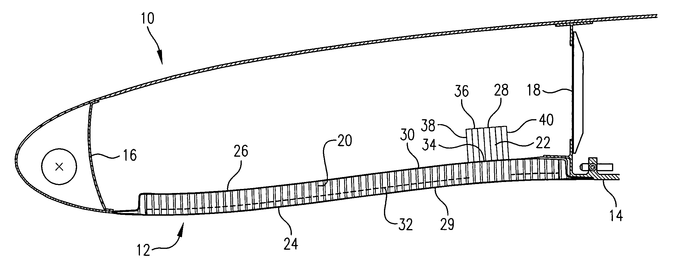
[0020]FIG. 3 illustrates an inlet 10 of a nacelle constructed in accordance with an embodiment of the invention. The inlet 10 comprises an acoustic barrel 12 forming at least a portion of an inner wall 14 of the inlet 10, a forward bulkhead 16, and an aft bulkhead 18. The acoustic barrel may form a substantially continu...


PUM


Abstract

An inlet of an aircraft nacelle having an acoustic barrel configured to reduce engine fan flutter by attenuating various frequencies. The acoustic barrel may comprise an acoustic panel of a honeycomb configuration sandwiched between a first back sheet and a face sheet and extending from a forward bulkhead to an aft bulkhead of the inlet. The acoustic barrel may further comprise a deep liner section bonded to and sandwiched between the first back sheet and a second back sheet. The deep liner section may have a narrower width than the acoustic panel and may be located proximate the aft bulkhead. The sections of the first back sheet, the face sheet, and a septum of the acoustic panel may be perforated and may contain additional holes formed in portions aligned radially inward of the deep liner section.

Description

BACKGROUND[0001]1. Field[0002]The present invention relates to aircraft components. More particularly, the invention relates to an apparatus for improving acoustic attenuation within an inlet of a nacelle.[0003]2. Related Art[0004]An aircraft nacelle (A) surrounds an aircraft's engine (B) and typically comprises a fan cowl (C), a thrust reverser (D), and an inlet (E), as illustrated in FIG. 1. The inlet (E) typically comprises an outer barrel panel (F), a forward bulkhead (G), an aft bulkhead (H), a thermal anti-ice spray tube (I), a lip skin (J), and an acoustic barrel (K), also referred to as an acoustic panel, as illustrated in FIG. 2.[0005]The acoustic barrel (K) is designed to provide acoustic attenuation, reducing engine and engine fan noise. For example, the acoustic barrel (K) can be made of a sandwich honeycomb panel, shaped to comprise a plurality of honeycomb cells. However, prior art acoustic panels are insufficient under certain conditions for reducing fan flutter cause...

Claims


Application Information

Patent Timeline
Patent Type & Authority Patents(United States)
IPC IPC(8): F02K1/82E04B1/82B64D33/02F02K1/78E04B1/74
CPCB64D33/02F02C7/045B64D2033/0206
Inventor STERNBERGER, JOE E.STRUNK, JOHN T.
Owner ROLLS ROYCE DEUT LTD & CO KG
Why Eureka
Eureka Blog
Learn More