Panelboard for fusible switching disconnect devices
a panelboard and disconnect device technology, applied in the direction of protective switch details, protective switch operating/release mechanisms, substation/switching arrangement casings, etc., can solve the problems of commercial difficulty of a faulty panelboard
- Summary
- Abstract
- Description
- Claims
- Application Information
AI Technical Summary
Problems solved by technology
Method used
Image
Examples
eighth embodiment
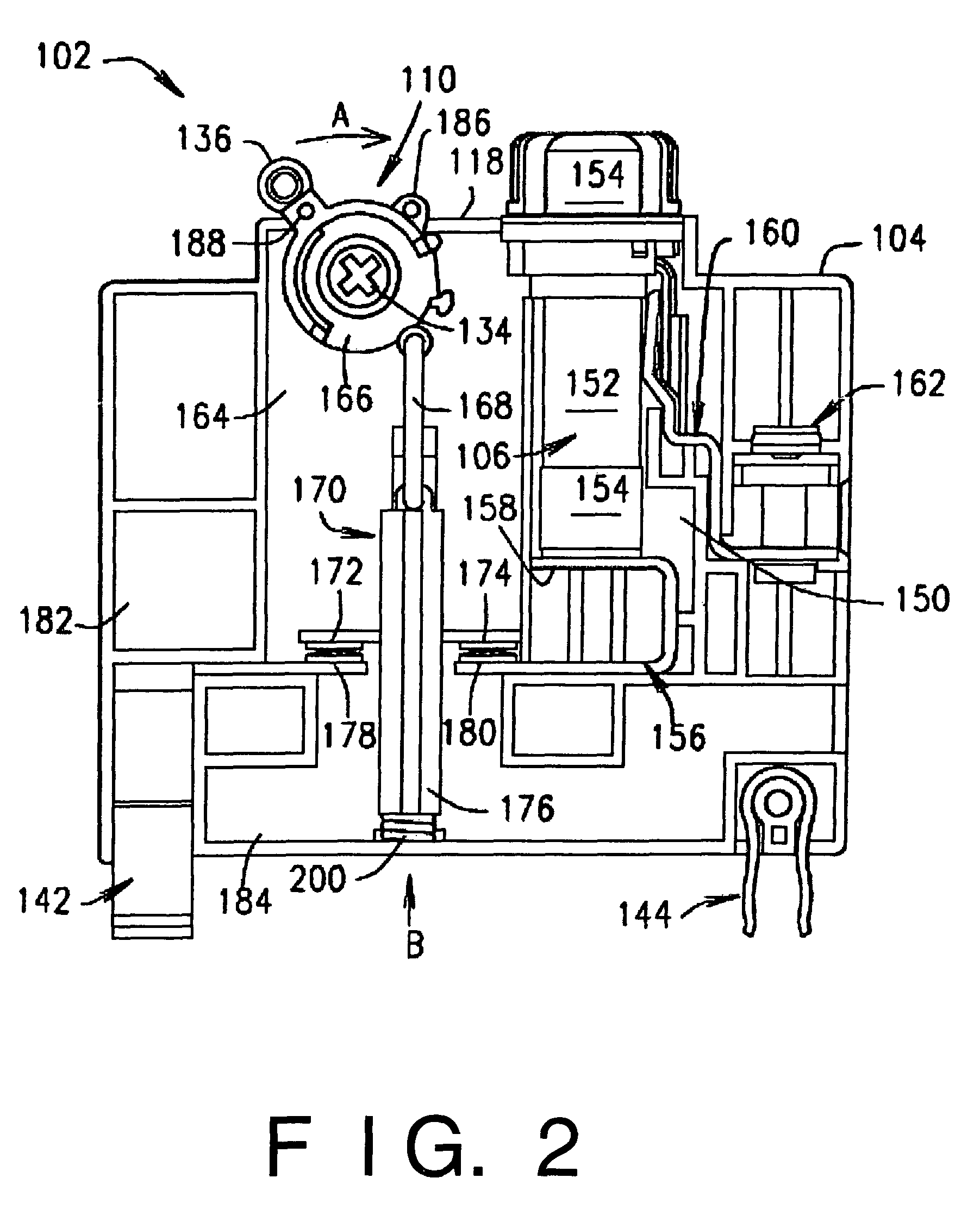
[0085]FIG. 12 is a perspective view of a fusible switching disconnect module 410 that, like the foregoing embodiments, includes a nonconductive housing 412, a switch actuator 414 extending through a raised upper surface 415 of the housing 412, and a cover 416 that provides access to a fuse receptacle (not shown in FIG. 12) within the housing 412 for installation and replacement of an overcurrent protection fuse (also not shown in FIG. 12). Like the foregoing embodiments, the housing 412 includes switchable and stationary contacts (not shown in FIG. 12) that complete or break an electrical connection through the fuse in the housing 412 via movement of an actuator lever 417.
[0086]A DIN rail mounting slot 418 may be formed in a lower edge 420 of the housing 412, and the DIN rail mounting slot 418 may be dimensioned, for example, for snap-fit engagement and disengagement with a 35 mm DIN rail by hand and without a need of tools. The housing 412 may also include openings 422 that may be ...
ninth embodiment
[0101]FIG. 17 is a perspective view of a fusible switching disconnect module 500 that, like the foregoing embodiments, includes a single pole housing 502, a switch actuator 504 extending through a raised upper surface 506 of the housing 502, and a cover 508 that provides access to a fuse receptacle (not shown in FIG. 17) within the housing 502 for installation and replacement of an overcurrent protection fuse (also not shown in FIG. 17). Like the foregoing embodiments, the housing 502 includes switchable and stationary contacts (not shown in FIG. 17) that connect or disconnect an electrical connection through the fuse in the housing 502 via movement of an actuator lever 510.
[0102]Similar to the module 410, the module 500 may include a DIN rail mounting slot 512 formed in a lower edge 514 of the housing 502 for mounting of the housing 502 without a need of tools. The housing 502 may also include an actuator opening 515 providing access to the body of the switch actuator 504 so that t...
tenth embodiment
[0121]FIGS. 23 and 24 illustrate a fusible switching disconnect device 600 including a disconnect module 500 and an auxiliary contact module 602 coupled or ganged to the housing 502 in a side-by-side relation to the module 500 via the openings 516 (FIG. 17) in the module 500.
[0122]The auxiliary contact module 602 may include a housing 603 generally complementary in shape to the housing 502 of the module 500, and may include an actuator 604 similar to the actuator 504 of the module 500. An actuator link 606 may interconnect the actuator 604 and a sliding bar 608. The sliding bar 608 may carry, for example, two pairs of switchable contacts 610 spaced from another. One of the pairs of switchable contacts 610 connects and disconnects a circuit path between a first set of auxiliary terminals 612 and rigid terminal members 614 extending from the respective terminals 612 and each carrying a respective stationary contact for engagement and disengagement with the first set of switchable cont...
PUM
 Abstract
Description
Claims
Application Information
 - R&D
- Intellectual Property
- Life Sciences
- Materials
- Tech Scout
- Unparalleled Data Quality
- Higher Quality Content
- 60% Fewer Hallucinations
Browse by: Latest US Patents, China's latest patents, Technical Efficacy Thesaurus, Application Domain, Technology Topic, Popular Technical Reports.
© 2025 PatSnap. All rights reserved.Legal|Privacy policy|Modern Slavery Act Transparency Statement|Sitemap|About US| Contact US: help@patsnap.com


