
Electrode location mapping system and method

a technology for electrode position and location mapping, applied in the field of electromechanical location mapping system and method, can solve the problems of affecting the clinical outcome of patients,

Inactive Publication Date: 2010-12-14
MEDTRONIC INC
View PDF18 Cites 47 Cited by
  • Summary
  • Abstract
  • Description
  • Claims
  • Application Information

AI Technical Summary

Benefits of technology

This approach facilitates accurate three-dimensional positioning of ablation electrodes, enhancing the precision and safety of cardiac ablation procedures by integrating location mapping with anatomical ultrasound imaging, even with less costly two-dimensional systems, thereby improving therapy success and reducing the risk of complications.

Problems solved by technology

Pathologic tachycardia results in impaired hemodynamics, i.e. decreased cardiac output.
Despite of the recent advances in electropharmacology, every antiarrhythmic drug is not effective in every patient.
Drugs also provoke side effects, which can be hazardous to the patient.
One of the challenges in to a clinician in performing an ablation procedure is the exact positioning of the ablation electrode within the heart.
Limitations of X-ray methods, however, include poor imaging of soft tissues, i.e. papillary muscle, interventricular septa, and so forth.
However, the intracardiac potential is discontinuous being characterized with intrinsic deflection, which is repetitive at the frequency of the heartbeats.
Although three-dimensional ultrasonic imaging is available, the currently high cost of three-dimensional systems generally prohibits widespread use.
The clinician is required to envision the catheter position in three-dimensions, which makes exact positioning of the catheter a challenge.

Method used


Image

  • Electrode location mapping system and method
  • Electrode location mapping system and method
  • Electrode location mapping system and method

Examples


Embodiment Construction

[0014]The following detailed description is exemplary in nature and is not intended to limit the scope, applicability, or configuration of the invention in any way. Rather, the following description provides a practical illustration for implementing exemplary embodiments of the invention.

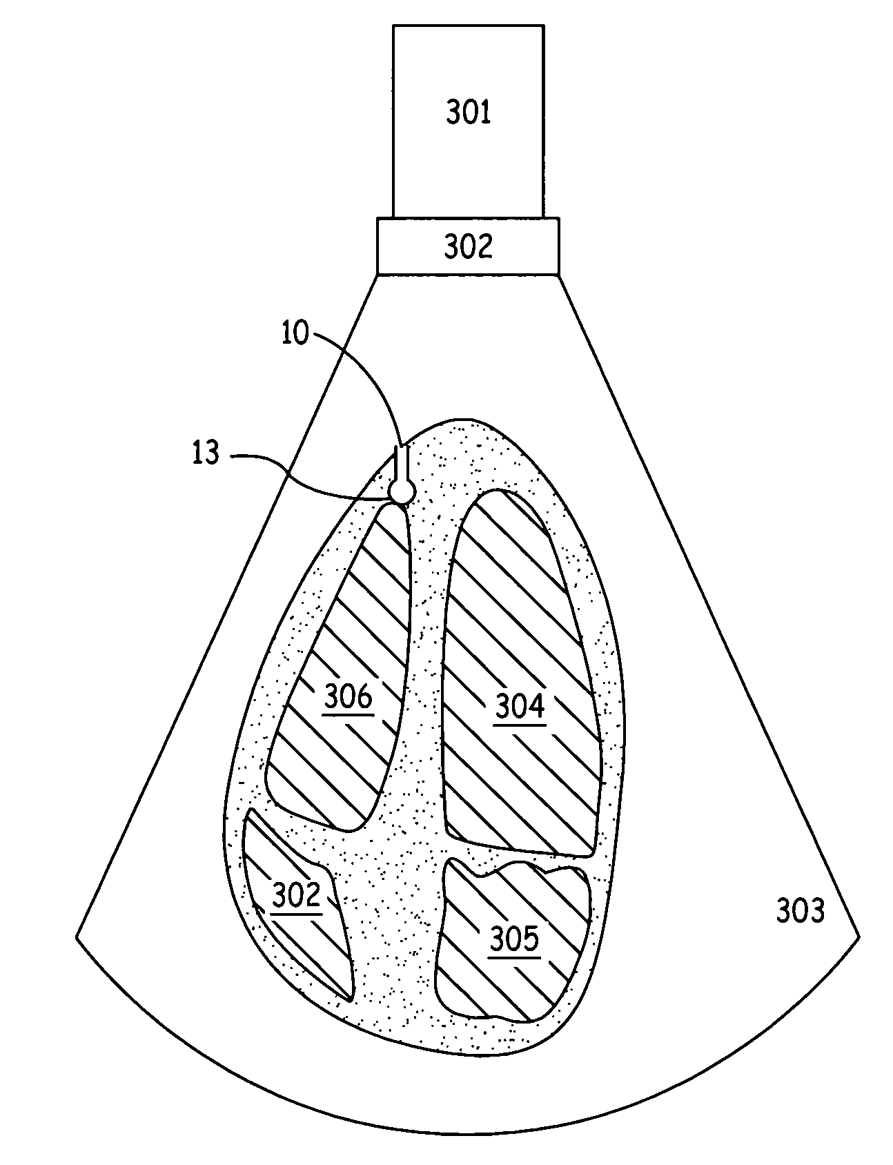
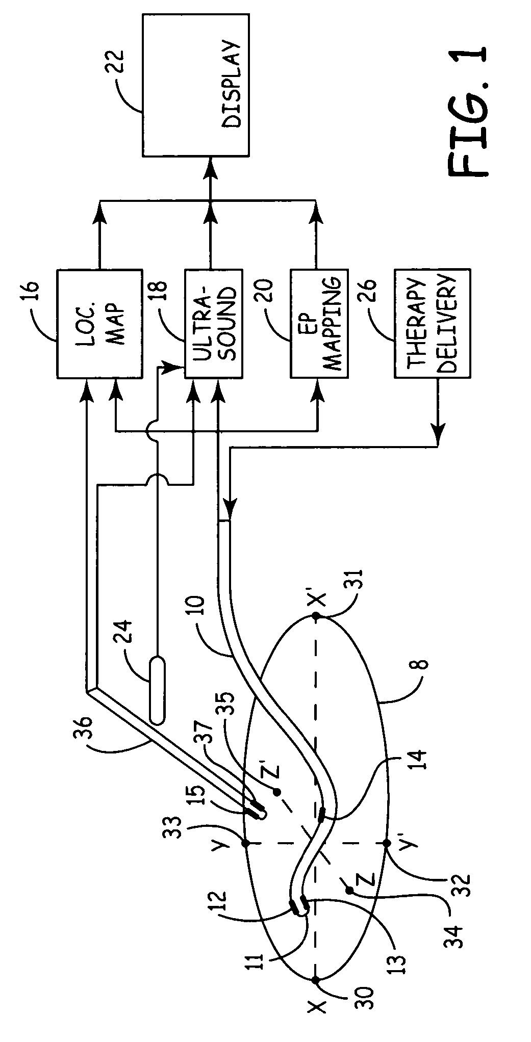
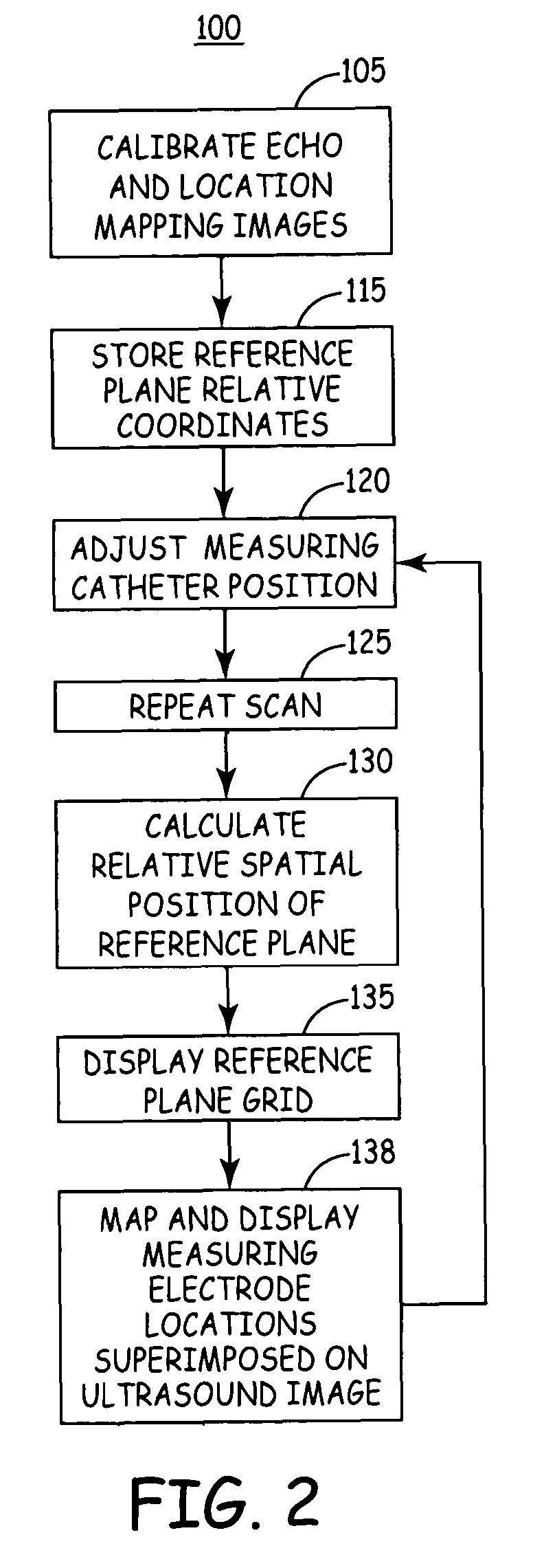
[0015]FIG. 1 is a schematic diagram of a mapping system in accordance with an embodiment of the present invention. The mapping system includes a measuring catheter 10 which may be mapped in three dimensions and used for delivering a medical therapy; a reference catheter 36 used in a calibration procedure for aligning ultrasound views and location mapping views; orthogonally-arranged electrodes 30, 31, 32, 33, 34, and 35 defining a local coordinate system of a mapping volume 8; and an ultrasound scanning probe 24. The measuring catheter 10, one or more reference catheters 36, orthogonally-arranged electrodes 30 through 35, and ultrasound scanning probe are coupled to appropriate components included i...


PUM


Abstract

A mapped location of one or more electrodes within an electrical mapping volume is superimposed onto an ultrasound image corresponding to the electrical mapping volume.

Description

FIELD OF THE INVENTION[0001]The present invention relates generally to systems and methods for mapping an electrode position within a body, and more specifically to a system and method for superimposing an electrically mapped location of one or more electrodes onto a corresponding ultrasound image.BACKGROUND OF THE INVENTION[0002]The following background describes one context in which embodiments of the present invention may be practiced and should not be viewed as limiting the scope of the present invention as set forth in the appended claims.[0003]Tachycardia is the condition of an accelerated pulse rate. Natural tachycardia occurs in physical exercise and emotional stress because of the sympathetic nervous tone and increase of the circulatory catecholamine concentration. The most important quality of natural tachycardia is the resultant increase in cardiac output. Pathologic tachycardia results in impaired hemodynamics, i.e. decreased cardiac output. The electrophysiology discrim...

Claims


Application Information

Patent Timeline
Patent Type & Authority Patents(United States)
IPC IPC(8): A61B8/00A61B5/042A61B5/06A61B8/08
CPCA61B5/06A61B8/0833A61B8/0841A61B8/4245A61B8/5238A61B5/0422A61B8/0883A61B2019/5253A61B2034/2053A61B5/743A61B5/062A61B5/287
Inventor FEREK-PETRIC, BOZIDAR
Owner MEDTRONIC INC
Learn More