
Hybrid spin/fin stabilized projectile

a projectile and spin stabilizer technology, applied in the field of projectiles, can solve the problems of high aerodynamic drag and required stability, and achieve the effect of reducing the spin rate of the projectil

Active Publication Date: 2010-12-14
RAYTHEON CO
View PDF6 Cites 19 Cited by
  • Summary
  • Abstract
  • Description
  • Claims
  • Application Information

AI Technical Summary

Benefits of technology

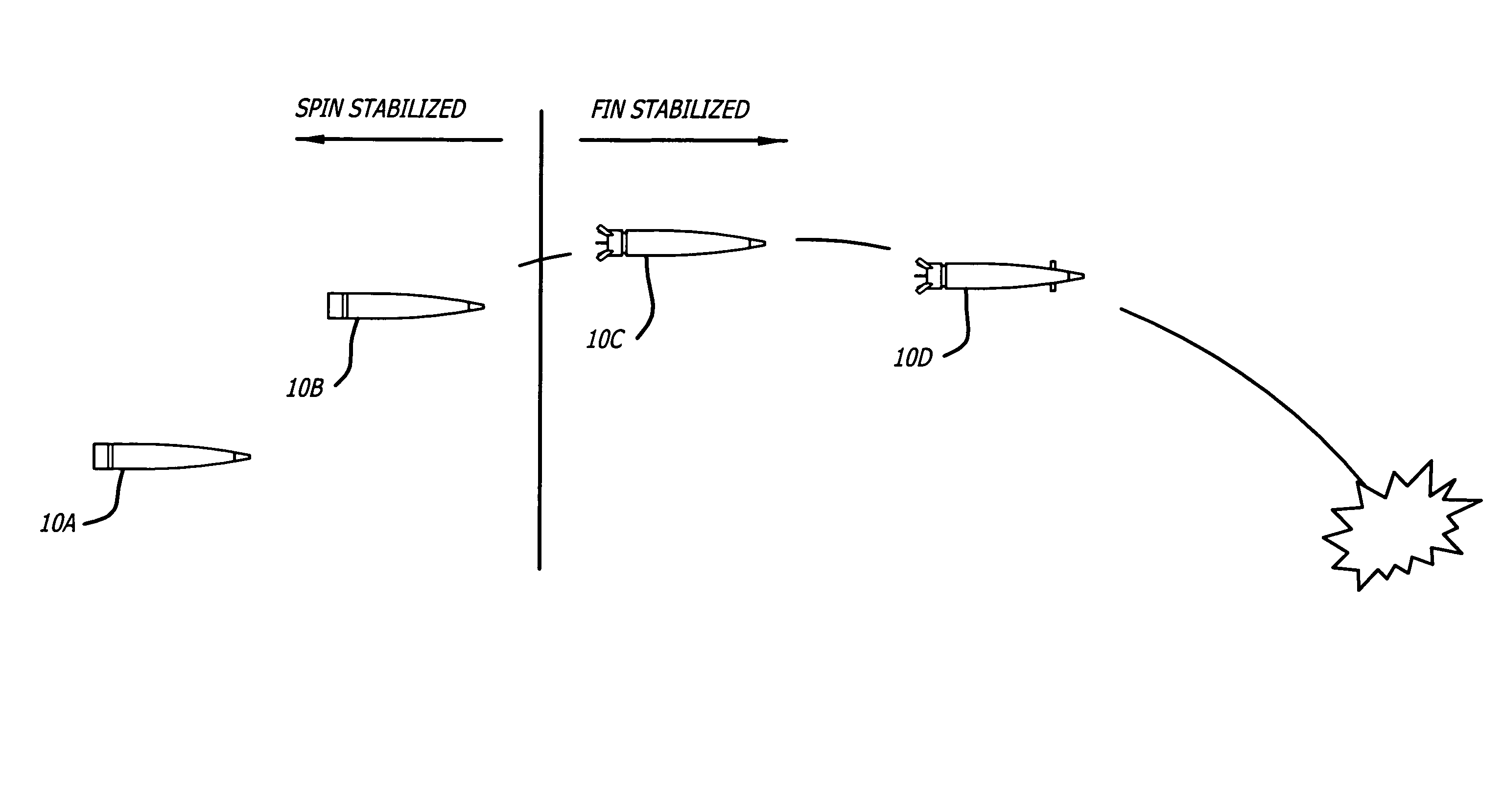
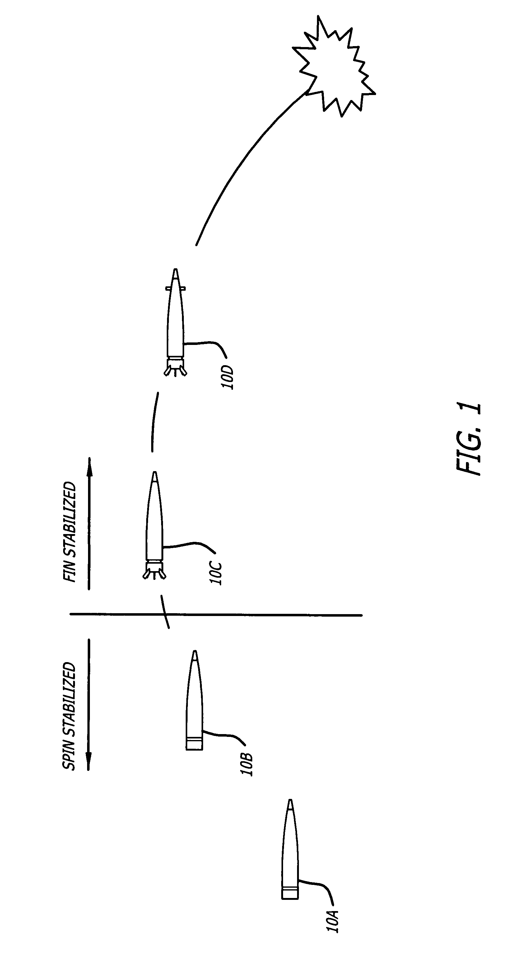
The present invention is a hybrid spin / fin stabilized projectile that includes a body, a first mechanism for spin stabilizing the body, and a second mechanism for fin stabilizing the body. The projectile also includes a rifling band and a plurality of folding fins that can be locked in an undeployed position during the initial spin stabilized mode and unlocked to deploy at a predetermined time to switch the projectile to fin stabilization during the second mode. The projectile also includes a mechanism for reducing the spin of the projectile to a rate compatible with guided flight during the fin stabilized mode. The invention provides improved stability and control during flight.

Problems solved by technology

Unfortunately, the tail fins which provide the required stability also provide high aerodynamic drag.

Method used


Image

  • Hybrid spin/fin stabilized projectile
  • Hybrid spin/fin stabilized projectile
  • Hybrid spin/fin stabilized projectile

Examples


Embodiment Construction

[0019]Illustrative embodiments and exemplary applications will now be described with reference to the accompanying drawings to disclose the advantageous teachings of the present invention.

[0020]While the present invention is described herein with reference to illustrative embodiments for particular applications, it should be understood that the invention is not limited thereto. Those having ordinary skill in the art and access to the teachings provided herein will recognize additional modifications, applications, and embodiments within the scope thereof and additional fields in which the present invention would be of significant utility.

[0021]The present invention provides a simple, low cost approach to extending the ballistic range of a guided projectile. It combines the low drag performance of a spin stabilized projectile during initial flight with that of a fin stabilized projectile during guided flight. Therefore, the projectile obtains additional range during that portion of fl...


PUM


Abstract

A hybrid spin / fin stabilized projectile. The novel projectile includes a body, a first mechanism for spin stabilizing the body during a first mode, and a second mechanism for fin stabilizing the body during a second mode. In an illustrative embodiment, the projectile includes a rifling band adapted to engage with rifling in a gun during gun launch to impart a spin rate compatible with spin stabilization to the projectile, and a plurality of folding fins attached to an aft end of the body. A fin locking mechanism locks the fins in an undeployed position during the first mode and unlocks to deploy the fins at a predetermined time to switch the projectile to fin stabilization during the second mode. The projectile also includes a mechanism for reducing the spin of the projectile to a rate compatible with guided flight during the second mode.

Description

BACKGROUND OF THE INVENTION[0001]1. Field of the Invention[0002]The present invention relates to projectiles. More specifically, the present invention relates to systems and methods for stabilizing guided projectiles.[0003]2. Description of the Related Art[0004]Conventional projectiles are typically spin stabilized. With spin stabilization, the projectile rotates at a high spin rate around its longitudinal axis. This keeps the orientation of the projectile under control.[0005]Guided projectiles use a guidance system for navigating the projectile during at least part of its flight path. The guidance system usually requires the projectile to spin at a lower rate than is compatible with spin stabilization. For example, a typical artillery shell needs a spin rate of about 200-300 revolutions per second or more to achieve spin stabilization. In contrast, a typical projectile guidance system operates at spin rates of less than 10-12 revolutions per second.[0006]In order to achieve stabili...

Claims


Application Information

Patent Timeline
Patent Type & Authority Patents(United States)
IPC IPC(8): F42B10/00
CPCF42B10/14F42B10/26F42B10/54
Inventor HINSDALE, ANDREW J.DRYER, RICHARD
Owner RAYTHEON CO
Learn More