
Portable power distribution panel

a power distribution panel and portable technology, applied in the direction of gaseous cathodes, electric apparatus casings/cabinets/drawers, furniture parts, etc., can solve the problems of limited mobility, cumbersome transportation, and inability to have fixed electric power distribution systems, so as to achieve safe and easy configuration, easy transportation, and convenient use

Active Publication Date: 2010-12-07
GERBER MARTIN
View PDF29 Cites 31 Cited by
  • Summary
  • Abstract
  • Description
  • Claims
  • Application Information

AI Technical Summary

Benefits of technology

[0009]It is therefore an object of the present invention to provide a power distribution panel that is easily transported and is safely and easily configured to various configurations.

Problems solved by technology

There are, however, various sites and locations that require electric power and yet do not have fixed electric power distribution systems, for example, in the motion picture industry, convention and exhibit halls, indoor & outdoor events, and special events.
This panel, however, has limited mobility and is cumbersome to transport, for example, on stairs or over rugged terrain.
However, in order to change the panels it is very laborious due to the plurality of screws.
In addition, the screws that are utilized to mount the panels to the corner rails protrude into the interior of the cabinet and may cause damage to interior components, such as wiring.
In the event that a panel is replaced, there is a greater risk of damage or injury if, for example, an improperly sized screw is used.

Method used


Image

  • Portable power distribution panel
  • Portable power distribution panel
  • Portable power distribution panel

Examples


Embodiment Construction

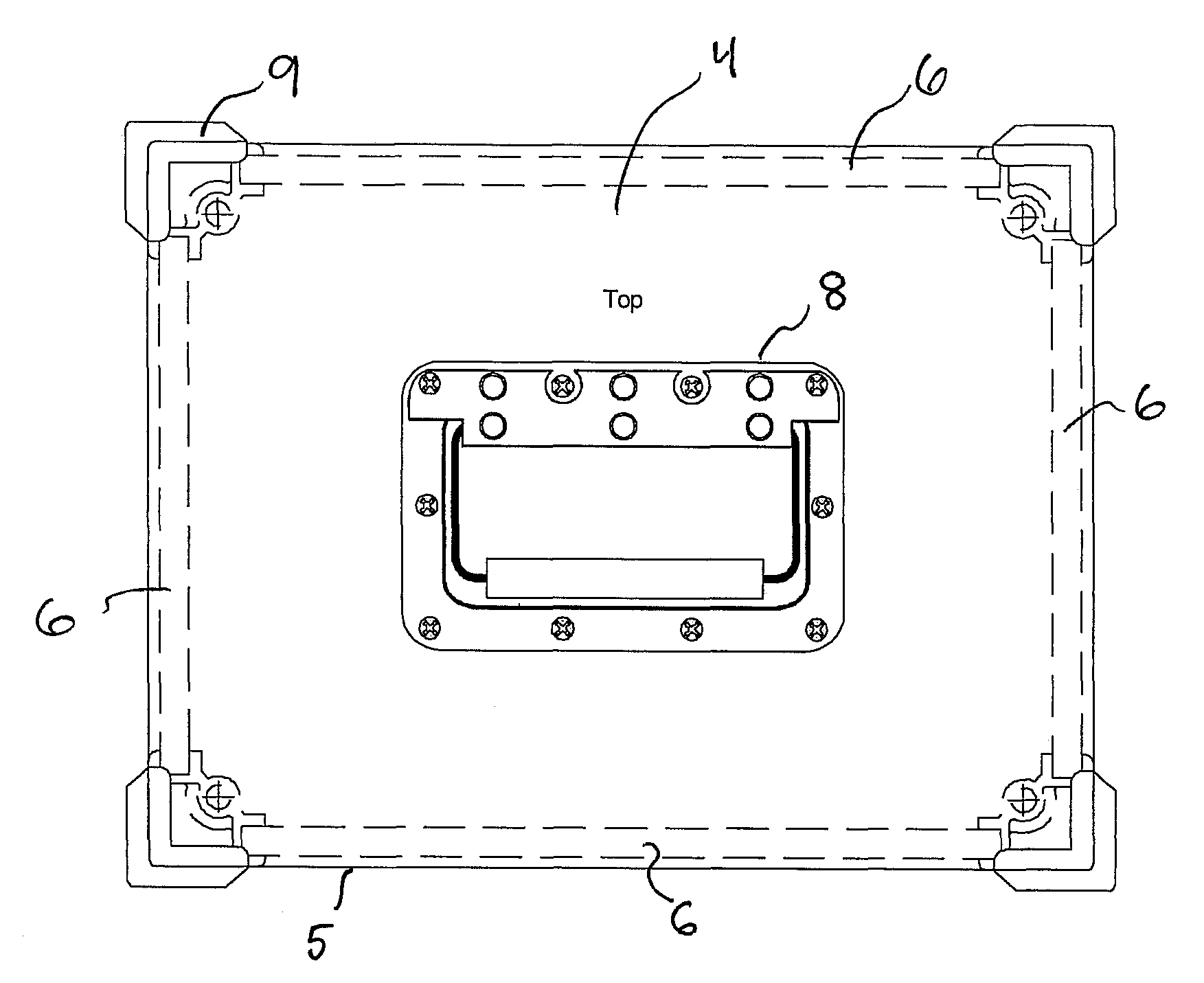
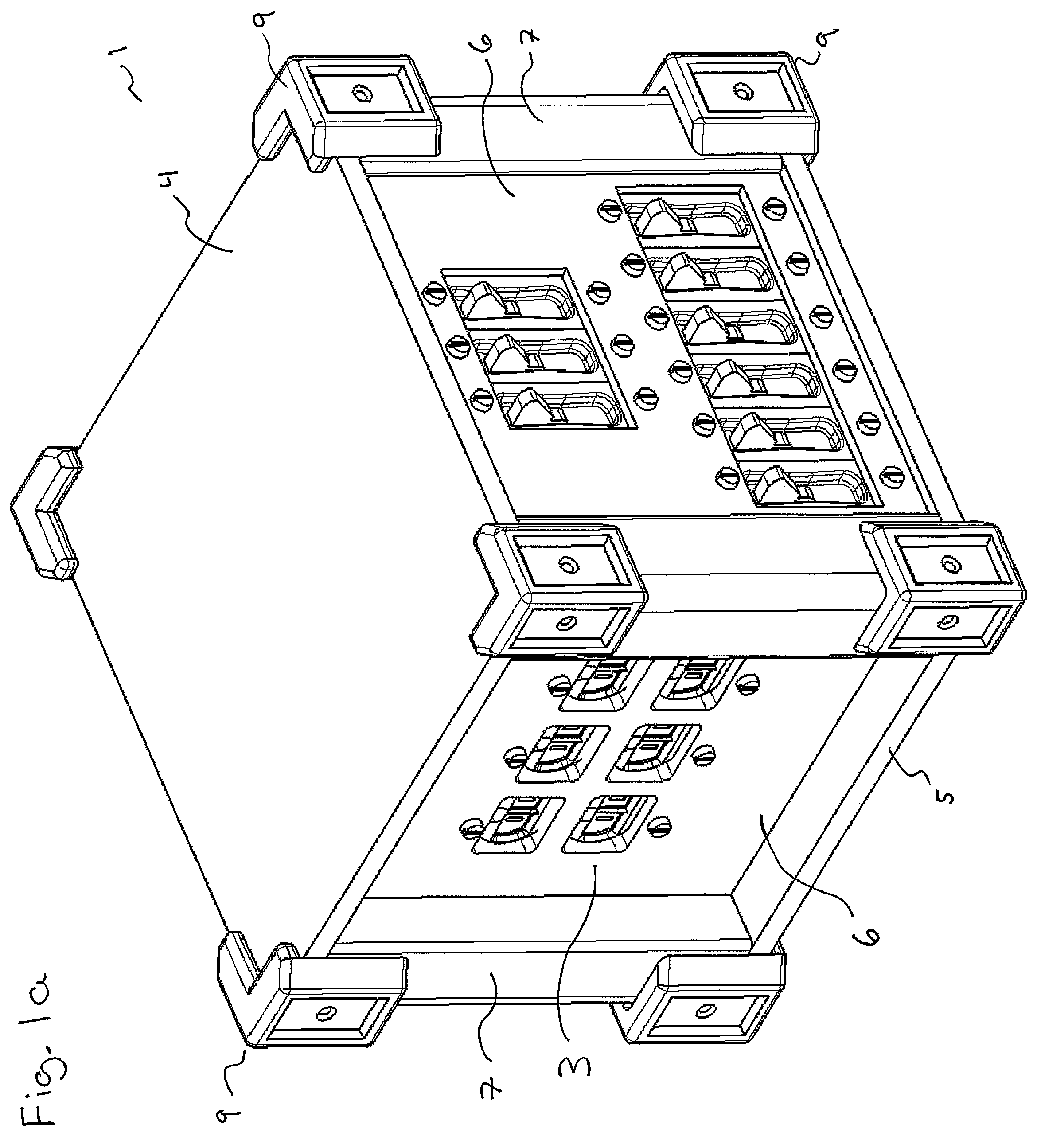
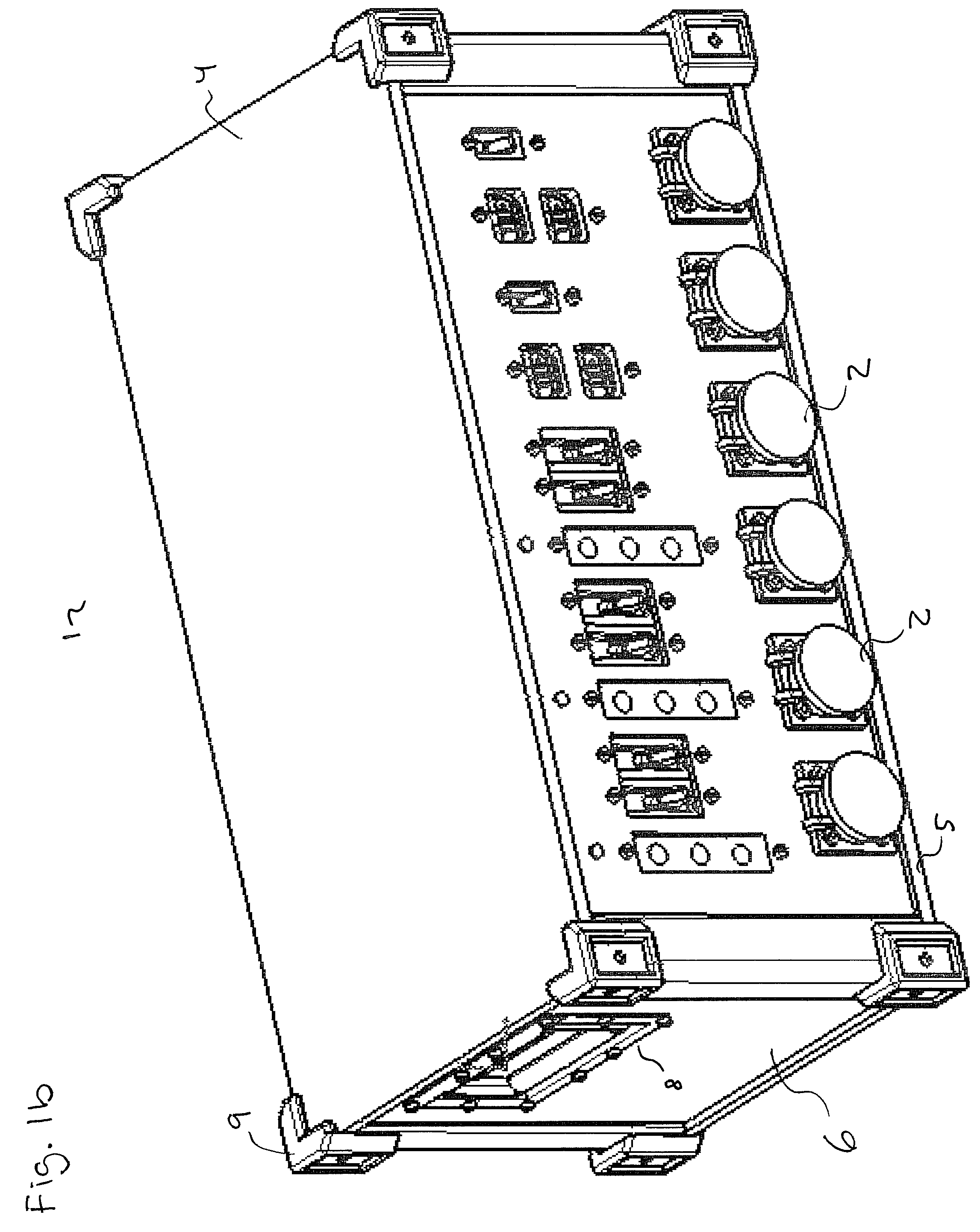
[0017]FIGS. 1a-c illustrate perspective views of different exemplary configurations of a power distribution box 1 that includes a plurality of inputs 2 for receiving a voltage and a plurality of outputs 3 for distributing the voltage or a lower voltage that is transformed by electrical components contained within the power distribution box 1. The power distribution box 1 is enclosed by an upper panel 4, a lower panel 5, and side panels 6. The upper panel 4, lower panel 5, and side panels 6 are removably arranged to one another via guide rails 7. In addition, a corner piece 9 may be provided, which can be fixedly secured to each corner to further protect the power distribution box 1.

[0018]The panels 4, 5, 6 provide a surface to attach electrical components and to protect the internal components from damage. Various electrical components, inputs 2, and outputs 3, can be mounted onto the panels in various configurations. These electrical components can include, for example, receptacles...


PUM


Abstract

A power distribution system is provided that includes an upper panel, a lower panel, a plurality of side panels, and a plurality of guide rails each having at least two insert slots formed therein that extend along a longitudinal axis of the guide rail. Each of the insert slots is configured to receive and fixedly hold an edge of the side panels. The upper panel and lower panel are each fixedly mounted to an opposite edge face of the guide rails thereby securing the side panels and guide rail between the upper panel and lower panel.

Description

BACKGROUND OF THE INVENTION[0001]1. Field of the Invention[0002]The present invention relates to portable power distribution equipment.[0003]2. Description of the Background Art[0004]Power distribution systems are used to distribute voltages for various applications. Conventional power distribution systems typically include a number of different circuit elements such as circuit breakers, input and output connectors, LED's, etc. These circuit elements are typically enclosed within a housing structure for safety and other reasons. The housing structure is then fixedly mounted in a building structure or at a specific outdoor location.[0005]There are, however, various sites and locations that require electric power and yet do not have fixed electric power distribution systems, for example, in the motion picture industry, convention and exhibit halls, indoor & outdoor events, and special events.[0006]U.S. Pat. No. 5,544,003 describes a portable power distribution panel. The distribution ...

Claims


Application Information

Patent Timeline
Patent Type & Authority Patents(United States)
IPC IPC(8): H02B1/52
CPCH02B1/52
Inventor GERBER, MARTIN
Owner GERBER MARTIN
Learn More