
Structural color display

a color display and structure technology, applied in the field of structural color display, can solve the problems of large power consumption, large brightness, and large surface area of electronic paper, and achieve the effects of low energy loss, sufficient brightness, and high brightness

Inactive Publication Date: 2010-12-07
KONICA MINOLTA BUSINESS TECH INC
View PDF14 Cites 28 Cited by
  • Summary
  • Abstract
  • Description
  • Claims
  • Application Information

AI Technical Summary

Benefits of technology

"The present invention is a structural color display that shows various colors using a single image display sheet. It is designed to show a high-brightness image with low power consumption. The display uses a pattern image forming member that controls the reflection of light from a light source to enter the image display sheet. The structural color display exhibits high visual security and low energy loss, making it a highly efficient and effective display."

Problems solved by technology

However, a general liquid crystal display has problems such that large power consumption is required, and the image surface of the electronic paper tends to darken since a color filter is generally employed, for example, to vary colors, and further, the image surface thereof becomes darker when filters such as a polarizing filter is employed to improve visual security.
Therefore, a display by which an image can be visually recognized exhibiting sufficient brightness at low electrical power consumption has not been realized.

Method used


Image

  • Structural color display
  • Structural color display
  • Structural color display

Examples


examples 2 and 3

For Preparation of Particle for Color Showing Layer

[0100]The particles [2] and [3] for color showing layer comprising a highly monodispersed polystyrene were prepared in a similar manner to Example 1 for the preparation of particle for color showing layer except that the amount of the sodium dodecyl sulfonate for the preparation of the surfactant solution [A] of Example 1 was changed to 0.37 parts by mass and 0.34 parts by mass for the particles [2] and [3] respectively The average particle diameter and the CV value for each of the particles [2] and [3] are given in Table 1.

example 1

For Preparation of Image Display Sheet

[0101]A suspension solution incorporating the particle [1] for color showing layer in an amount of 20% by mass was prepared, which was then applied onto a transparent PET film of 50 μm in thickness to 30 μm in thickness containing water, and then dried to prepare the display sheet comprising the coated film of 4 μm in thickness. On the surface of the above coated film, polyethylene terephthalate (PET) was applied as a protective layer, and the display layer was subjected to a fixing treatment by re-drying, to prepare the image display sheet [1].

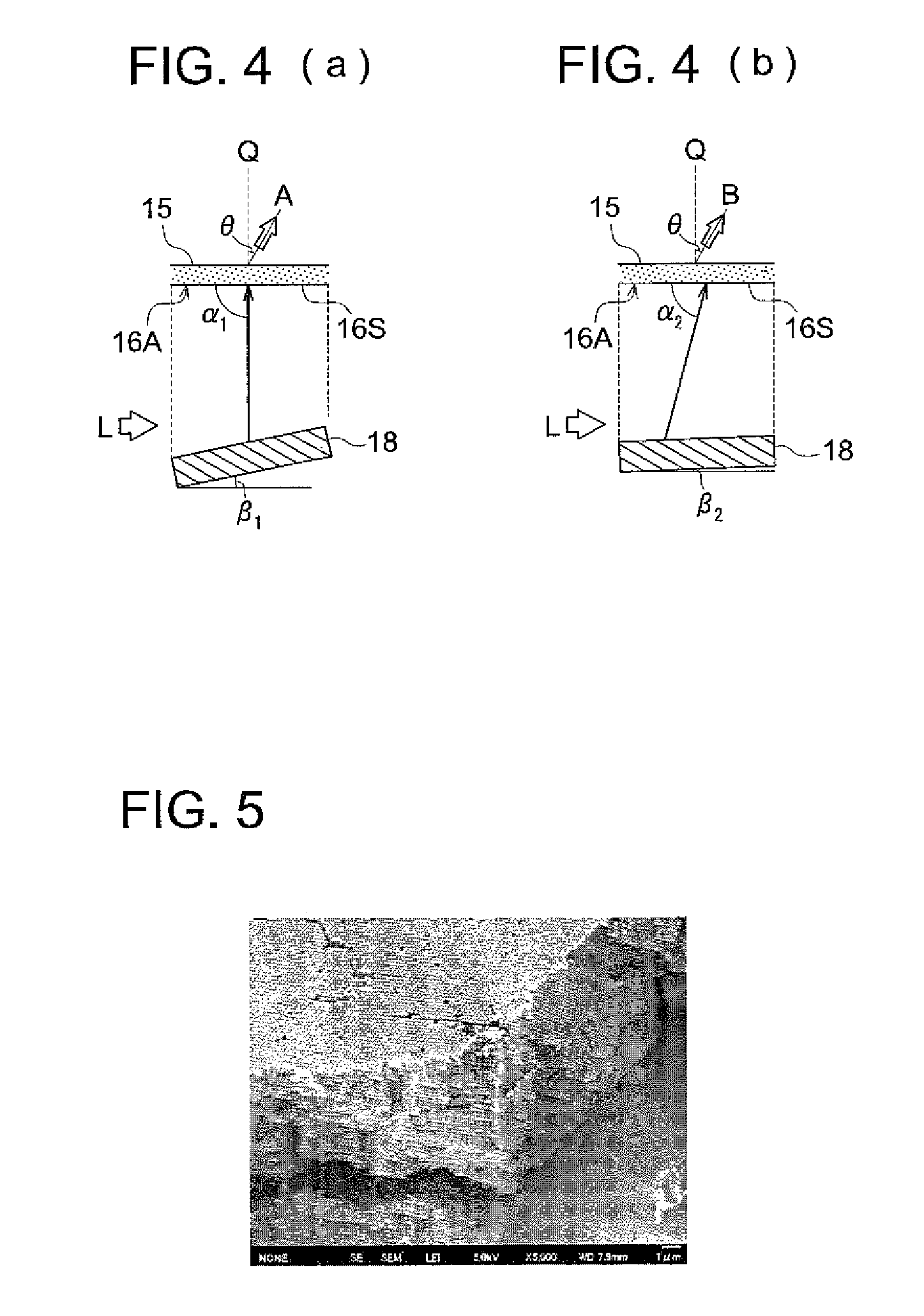
[0102]The above image display sheet [1] was subjected to a SEM observation, and as a result it was confirmed that the particles were regularly arranged in a hexagonal close-packed structure. The SEM photograph taken by the above SEM observation is shown in FIG. 5.

examples 2 to 3

For Preparation of Image Display Sheet

[0103]The image display sheets [2] to [3] were prepared in a similar manner to the preparation of the image display sheet [1] except that the particle [1] for color showing layer was change to each of the particles [2] to [3] for color showing layer.


PUM


Abstract

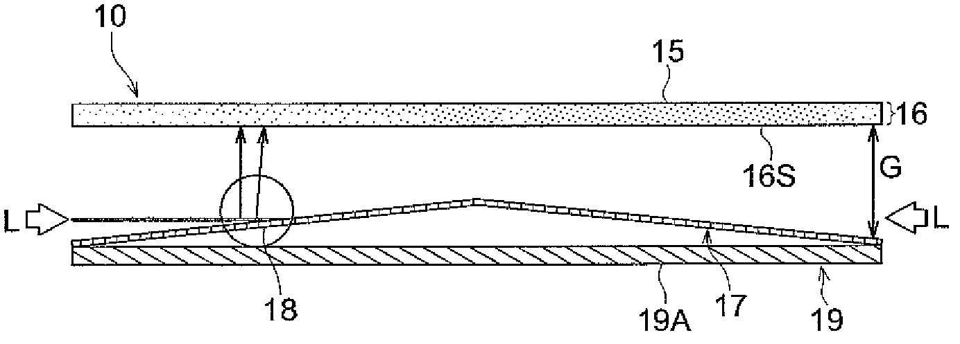
Disclosed is a structural color display including: (a) a pattern forming member which forms a plurality of cells each lined up in two dimension; and (b) a light transmissive image display sheet comprising a color showing layer which shows a structural color, the light transmissive image display sheet being faced to the pattern forming member, wherein each cell is independently controlled to reflect a light from a light source corresponding to an image pattern to be displayed, provided that the reflected light is made to enter in the image display sheet from a side facing the pattern forming member by a predetermined incident angle corresponding to the cell. The pattern image forming member comprises the element having a plurality of microscopic mirrors arranged in a rectangular array and being individually rotated.

Description

CROSS-REFERENCE TO RELATED APPLICATION[0001]This application is based on Japanese Patent Application No. 2007-318087 filed on Dec. 10, 2007 with Japan Patent Office, the entire content of which is hereby incorporated by reference.BACKGROUND OF THE INVENTION[0002]1. Technical Field[0003]The present invention relates to a structural color display utilizing color showing of a structural color.[0004]2. Description of Related Art[0005]Heretofore, a display which provides sufficient brightness at low electrical power consumption, and displays various colors has been demanded. Furthermore, a display which provides high visual security has been desired.[0006]However, a general liquid crystal display has problems such that large power consumption is required, and the image surface of the electronic paper tends to darken since a color filter is generally employed, for example, to vary colors, and further, the image surface thereof becomes darker when filters such as a polarizing filter is emp...

Claims


Application Information

Patent Timeline
Patent Type & Authority Patents(United States)
IPC IPC(8): G02B26/00G02B26/08
CPCG03B21/14G03B21/62
Inventor NISHIMURA, MOTOINAKAMURA, MITSUTOSHINAGASE, TATSUYASHIRAI, AYA
Owner KONICA MINOLTA BUSINESS TECH INC
Learn More