
Recumbent exerciser

a recumbent exerciser and pedal travel technology, applied in the field of recumbent exercisers, can solve the problems of requiring a significant time to be maintained, and the pedal travel may not be smooth,

Inactive Publication Date: 2010-12-07
STRENGTH MASTER FITNESS TECH
View PDF76 Cites 4 Cited by
  • Summary
  • Abstract
  • Description
  • Claims
  • Application Information

AI Technical Summary

Benefits of technology

"The present invention is a recumbent exerciser that includes two cams, one for each pedal and swinging arm, to provide consistent resistance during exercise. The direction of pedal operation is opposite to the direction of swinging arm movement. The transmission unit and resistance unit are located at different positions from the seat, allowing for easy maintenance without removing the seat. The technical effects of the invention include improved exercise efficiency and comfort."

Problems solved by technology

Nevertheless, the two pedals are operated to drive a single cam so that the trace that the pedals travel may not be smooth because the profile of the cam is not symmetrically designed and the center of the cam is not well positioned on the desired position.
The cam mechanism and the resistance unit include complicated structure which requires a significant time to be maintained.

Method used


Image

  • Recumbent exerciser
  • Recumbent exerciser
  • Recumbent exerciser

Examples


Embodiment Construction

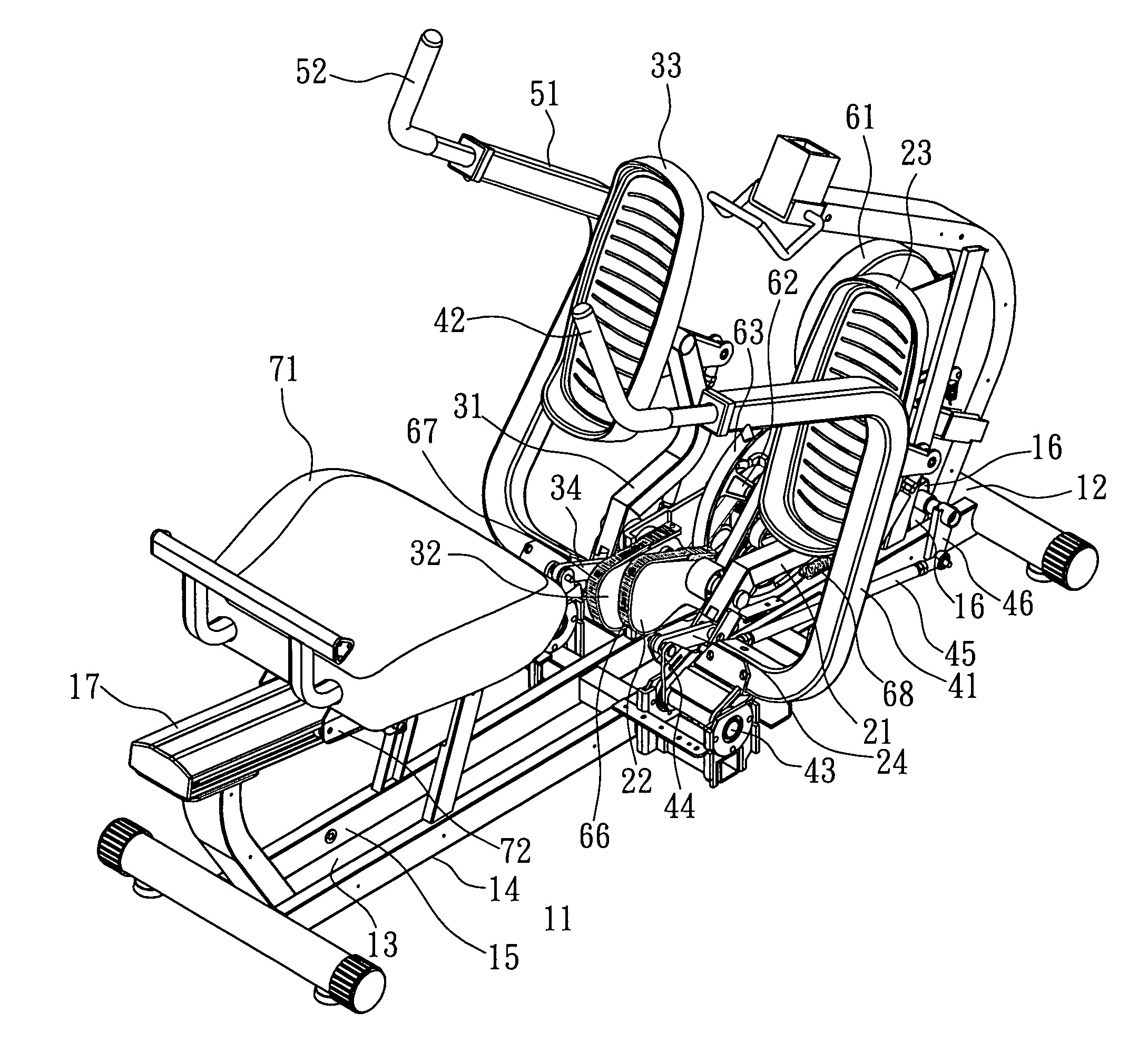
[0023]Referring to FIGS. 1 to 6, the recumbent exerciser of the present invention comprises a base 11, a right link 21, a left link 31, a right swinging arm 41, a left swinging arm 51, a resistance unit 61 and a seat 71.

[0024]The base 11 includes a front section 12 and a rear section 13, and is composed of a right frame 14 and a left frame 15 which is parallel to the right frame 14.

[0025]The mediate portion of the right link 21 is pivotably connected on the right side of the base 11 and located at the front section 12 of the base 11. A right cam 22 is connected to the right link 21 on the right frame 14 and a right pedal 23 is connected to the top end of the right link 21. The right link 21 has a first push link 24 connected to a distal end thereof and the right link 21 is driven by the right pedal 23 to drive the right cam 22.

[0026]The mediate portion of the left link 31 is pivotably connected on the left side of the base 11 and located at the front section 12 of the base 11. A lef...


PUM


Abstract

A recumbent exerciser includes a base, a right link and a left link are pivotably connected to the base and a right cam and a left cam are connected to the right link and the left link respectively. A right pedal and a left pedal are connected to two respective top ends of the right link and the left link, and a right swinging arm and a left swinging arm are connected to the right link and the left link. A resistance unit provides resistance to the right and left pedals and the right left swinging arms when the right and left cams are driven by operation of the user so as to exercise the user's hands and legs. The resistance unit is located remote from the seat so that the seat does not need to remove to maintain the resistance unit and the cams.

Description

FIELD OF THE INVENTION[0001]The present invention relates to an exerciser, and more particularly, to a recumbent exerciser which is easily maintained and is able to provide full range of exercise to user's hands and legs.BACKGROUND OF THE INVENTION[0002]A conventional recumbent exerciser generally includes a base on the floor and a frame is connected on the base, a treading mechanism is connected to the frame so that the user can operate two pedals. A swinging mechanism is located on a mediate portion of the frame and includes two co-axially installed arms to which the user's hands hold and swing to exercise both hands and feet.[0003]However, the resistance is generated only when the swinging arms move to a specific direction and there will be no resistance when the swinging arms move toward the opposite direction.[0004]U.S. Pat. No. 6,361,479 discloses a recumbent total body exerciser which includes two pedals on the front section of the base and the operation of the pedals drives ...

Claims


Application Information

Patent Timeline
Patent Type & Authority Patents(United States)
IPC IPC(8): A63B21/00G09B9/06
CPCA63B21/155A63B21/157A63B22/001A63B22/0056A63B21/225A63B2208/0238
Inventor WU, SHEN-YI
Owner STRENGTH MASTER FITNESS TECH
Learn More