Method for renaming a large number of registers in a data processing system using a background channel

a data processing system and register renaming technology, applied in the field of data processing systems, can solve the problems of increasing power consumption, disadvantageous large gate count, and associated disadvantageous large power consumption

Active Publication Date: 2010-11-30
ARM LTD
View PDF2 Cites 0 Cited by
  • Summary
  • Abstract
  • Description
  • Claims
  • Application Information

AI Technical Summary

Benefits of technology

[0014]The present technique recognizes that in practice the physical register specifiers of an instruction requiring a large number of physical register specifiers will in practice not all be consumed at one time and accordingly need not necessarily be generated and passed together along the instruction pipeline in a single operation. The present technique exploits this realisation by providing both a main channel and a background channel from the register renaming circuitry for outputting the register specifiers for further processing. Thus, an initial set of register specifiers and register specifiers for following program instructions may be output from the register renaming logic for further processing down the main channel. This provides that the initial register specifiers required for further processing to start execution of the program instruction requiring a large number of register specifiers are available without delay down the normal main channel and that following program instructions can also provide their register specifiers down the normal main channel. The background channel provides a mechanism whereby the remaining set of register specifiers for the instruction requiring a large number of register specifiers may be passed for further processing concurrently with other register specifiers being sent along the main channel.
[0015]As an example, consider a load / store multiple instruction of the ARM instruction set. Such an instruction may specify that, for example, eight registers be loaded with data values read from memory. This load / store multiple instruction is executed by a load / store unit which in the context of the system employing register renaming needs to be supplied with the register specifiers for the renamed set of physical registers in order that it can load the data values to the appropriate physical registers. However, such a load / store unit will typically have a finite capacity for loading data values in parallel and this may well be less than the total number of register loads which are to take place. Thus, if the load / store unit can be passed the register specifiers needed to start the overall load / store operation down the main channel and then fed subsequent register specifiers via the background channel, then it may be kept properly employed in executing the load / store multiple instruction without stalling at the renaming stage to allow all the renaming operations to be performed in one go; requiring large numbers of register specifiers to be passed in parallel from the renaming stage; or preventing subsequent program instructions from being able to pass their renaming physical register specifiers via the main channel whilst the remaining register specifiers.
[0016]Whilst it might be possible for the background channel to pass all of the remaining set of register specifiers out for further processing in a single operation, it is more efficient and more flexible to provide that the background channel outputs the remaining set of register specifiers as a sequence.

Problems solved by technology

A problem arises with register renaming techniques when handling program instructions which reference a large number of registers each requiring renaming.
The mechanisms necessary to support renaming of a large number of registers at one time require a disadvantageously large gate count and an associated disadvantageously large power consumption.
The passing of such a large number of renamed register specifiers in parallel along the instruction pipeline also requires a disadvantageous gate count and area penalty with an associated disadvantageous increase in the power consumption.
Whilst the above problems may not be significant in systems in which gate count, area and power consumption are not particular constraints, they do represent a significant problem in the context of small, inexpensive and power efficient processors in which it is desired to keep the gate count, area and power consumption low.
However, this would disadvantageously stall the following program instructions and would still require the renamed register specifiers to be passed in parallel across a disadvantageously broad path along the pipeline once they have been generated.

Method used


Image

  • Method for renaming a large number of registers in a data processing system using a background channel
  • Method for renaming a large number of registers in a data processing system using a background channel
  • Method for renaming a large number of registers in a data processing system using a background channel

Examples


Embodiment Construction

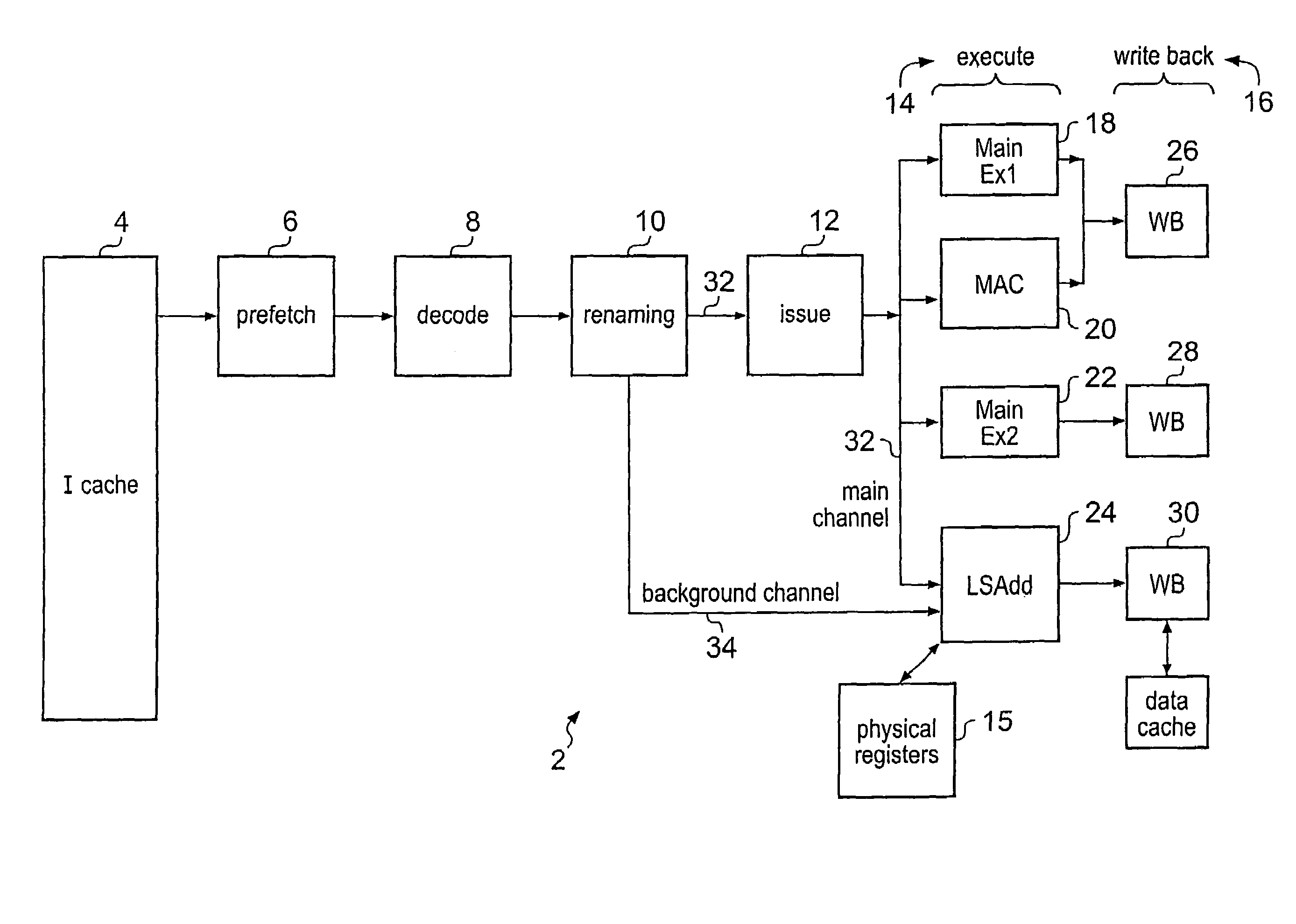
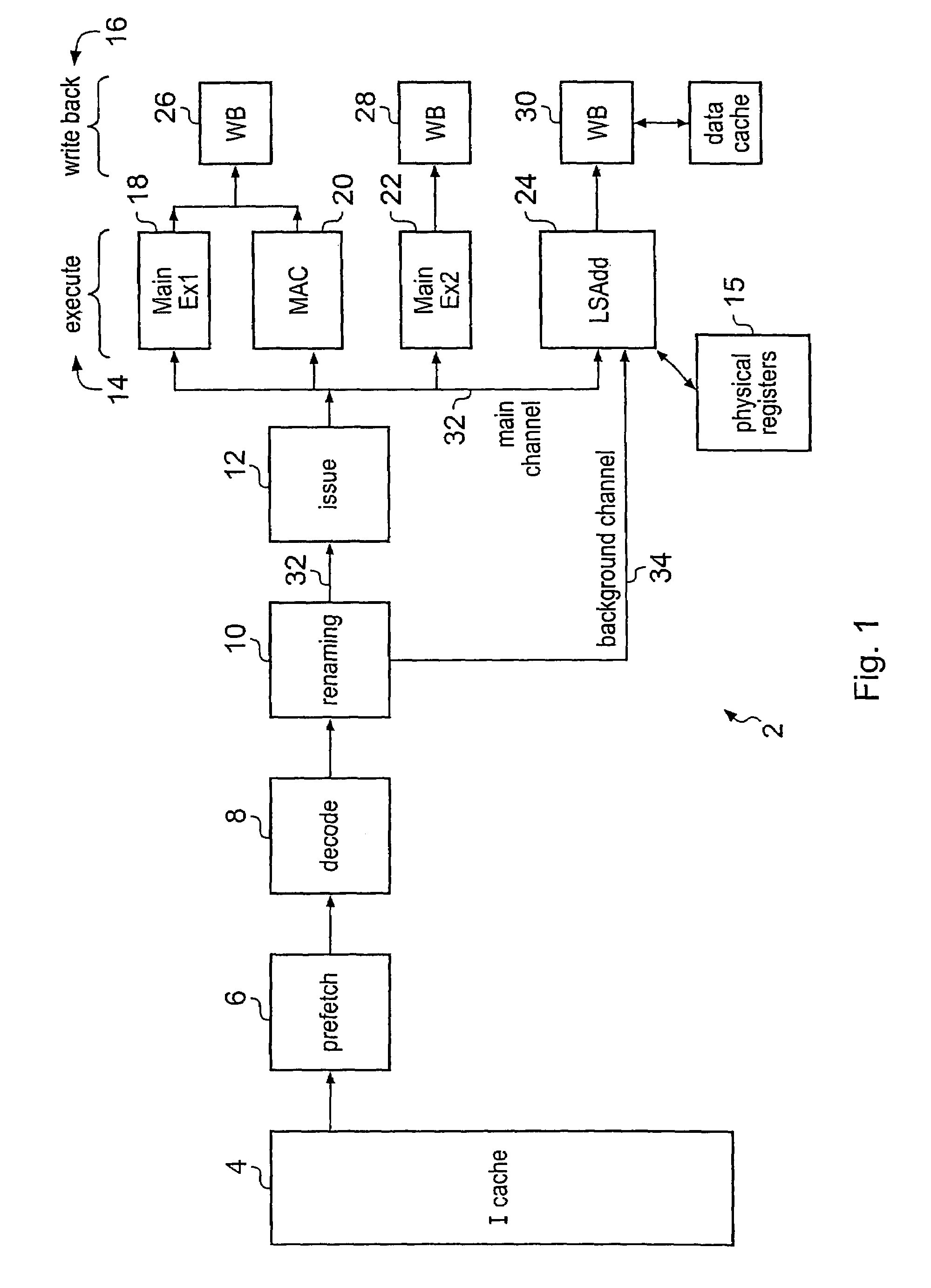
[0038]FIG. 1 shows a data processing apparatus 2 including an instruction cache 4 supplying program instructions into an instruction pipeline which includes a prefetch stage 6, a decode stage 8, a renaming stage 10 an issue stage 12, an execute stage 14 (with associated physical registers 15) and a writeback stage 16. It will be appreciated that in practice additional and / or alternative pipeline stages may be included within such a data processing apparatus 2. Furthermore, it will be appreciated that a complete data processing apparatus 2 will typically include many additional elements which will be apparent to those skilled in this technical field and have been omitted from FIG. 1 for the sake of clarity.

[0039]The execute stage 14 includes multiple units which may process program instructions in parallel including a first main execution unit 18, a multiply accumulate unit 20, a second main execution unit 22 and a load / store address stage 24 (which acts to send requests to a load / st...


PUM


Abstract

A processor 2 utilising register renaming executes program instructions requiring a large number of architectural register specifiers to be renamed by dividing the renaming tasks into an initial set and a remaining set. The initial set are performed first and the results passed via a main channel 32 for further processing. The remaining set are performed in sequence with the results being passed via a background channel 34 for further processing. This technique is particularly useful for performing renaming operations for load / store multiple LDM instructions.

Description

BACKGROUND OF THE INVENTION[0001]1. Field of the Invention[0002]This invention relates to data processing systems. More particularly, this invention relates to data processing systems using register renaming whereby register specifiers of an architectural set of registers are mapped to register specifiers of a physical set of registers.[0003]2. Description of the Prior Art[0004]Register renaming is a known technique for assisting in the support of out-of-order processing. Such systems are typically aimed at high performance applications where reducing gate count and reducing power consumption are not predominant considerations.[0005]A problem arises with register renaming techniques when handling program instructions which reference a large number of registers each requiring renaming. The mechanisms necessary to support renaming of a large number of registers at one time require a disadvantageously large gate count and an associated disadvantageously large power consumption. Further...

Claims


Application Information

Patent Timeline
Patent Type & Authority Patents(United States)
IPC IPC(8): G06F9/30G06F9/40
CPCG06F9/3836G06F9/384G06F9/3857G06F9/3858G06F9/30098
Inventor VINCENT, MELANIE EMANUELLE LUCIEBEGON, FLORENTAIRAUD, CEDRIC DENIS ROBERTLATAILLE, NORBERT BERNARD EUGENE
Owner ARM LTD
Why Eureka
Try Eureka