
Medical robotic system adapted to inhibit motions resulting in excessive end effector forces

a robotic system and end effector force technology, applied in the field of medical robotic systems, can solve the problems of reducing the surgeon's touch and contact force, unable to achieve even feasible procedures, and still having drawbacks

Active Publication Date: 2010-11-30
INTUITIVE SURGICAL OPERATIONS INC
View PDF6 Cites 1028 Cited by
  • Summary
  • Abstract
  • Description
  • Claims
  • Application Information

AI Technical Summary

Benefits of technology

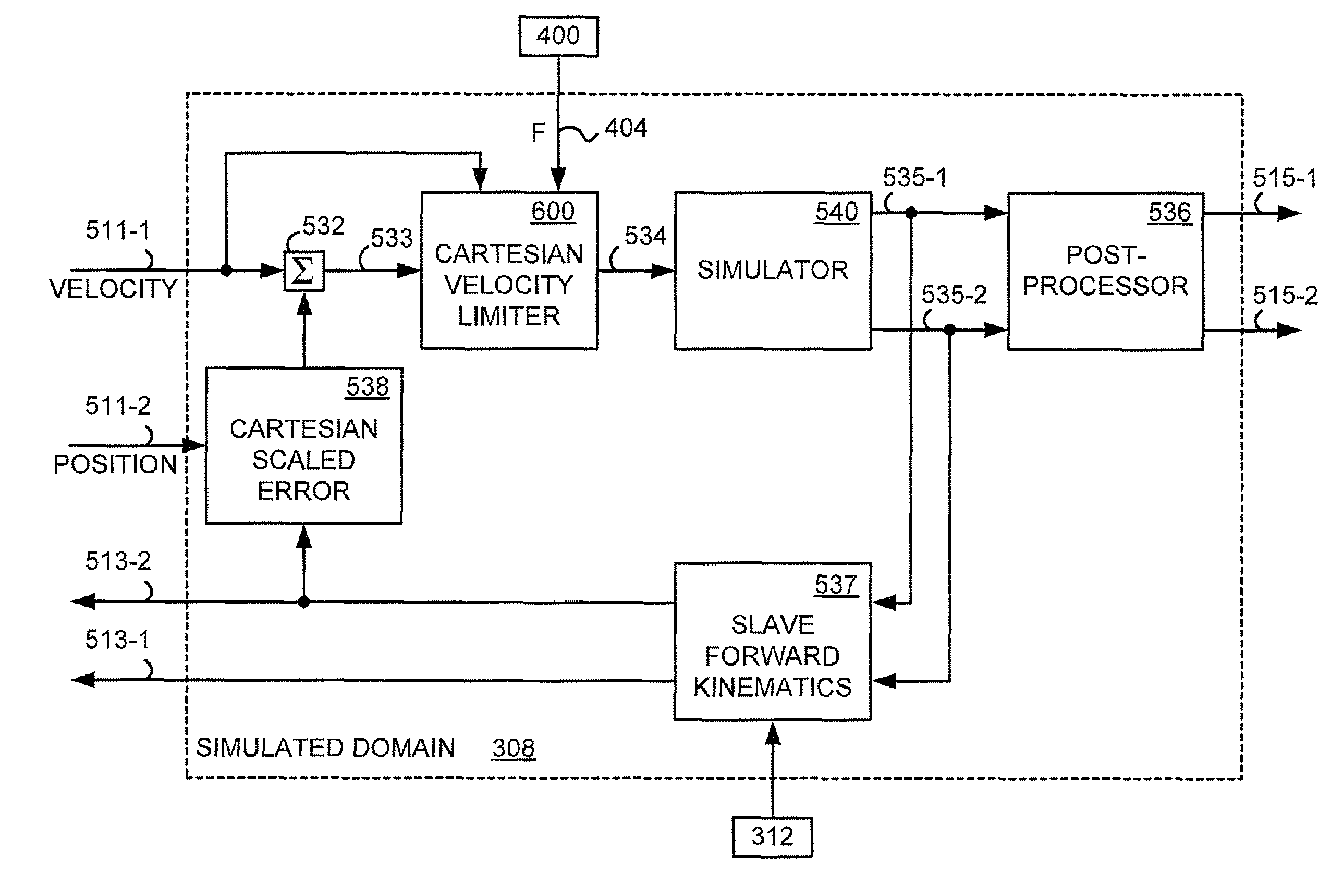
The present invention is a control system and method for a medical robotic system that prevents the end effector of a surgical instrument from causing excessive force during a medical procedure. The system receives commanded movement of the end effector and information of the force being exerted by it. The system then determines a reduced velocity of the commanded movement that would inhibit damage causing forces and controls the robotic manipulation of the surgical instrument accordingly. This prevents damage to the patient and ensures safe and efficient surgical procedures.

Problems solved by technology

Further, it may even allow the surgeon to perform medical procedures that are not even feasible using conventional open surgery techniques.
Although minimally invasive surgery enables keyhole access to many surgical sites while avoiding the loss of dexterity associated with earlier laparoscopic techniques, it still has the drawback compared to open surgery of reducing the surgeon's feeling of touch and of contact forces.
This may be difficult to do if the surgeon cannot feel how much force he or she is applying against the suture.
Unfortunately in practice such approaches all suffer from the general shortcoming of low fidelity and delayed reproduction of the slave force on the input devices.
Moreover force feedback systems in the literature always offer some risk of producing uncontrolled motions such as system instabilities, depending on the properties of the contact at the end effector and input device sides, and therefore, may not be generally suited for medical applications.

Method used


Image

  • Medical robotic system adapted to inhibit motions resulting in excessive end effector forces
  • Medical robotic system adapted to inhibit motions resulting in excessive end effector forces
  • Medical robotic system adapted to inhibit motions resulting in excessive end effector forces

Examples


Embodiment Construction

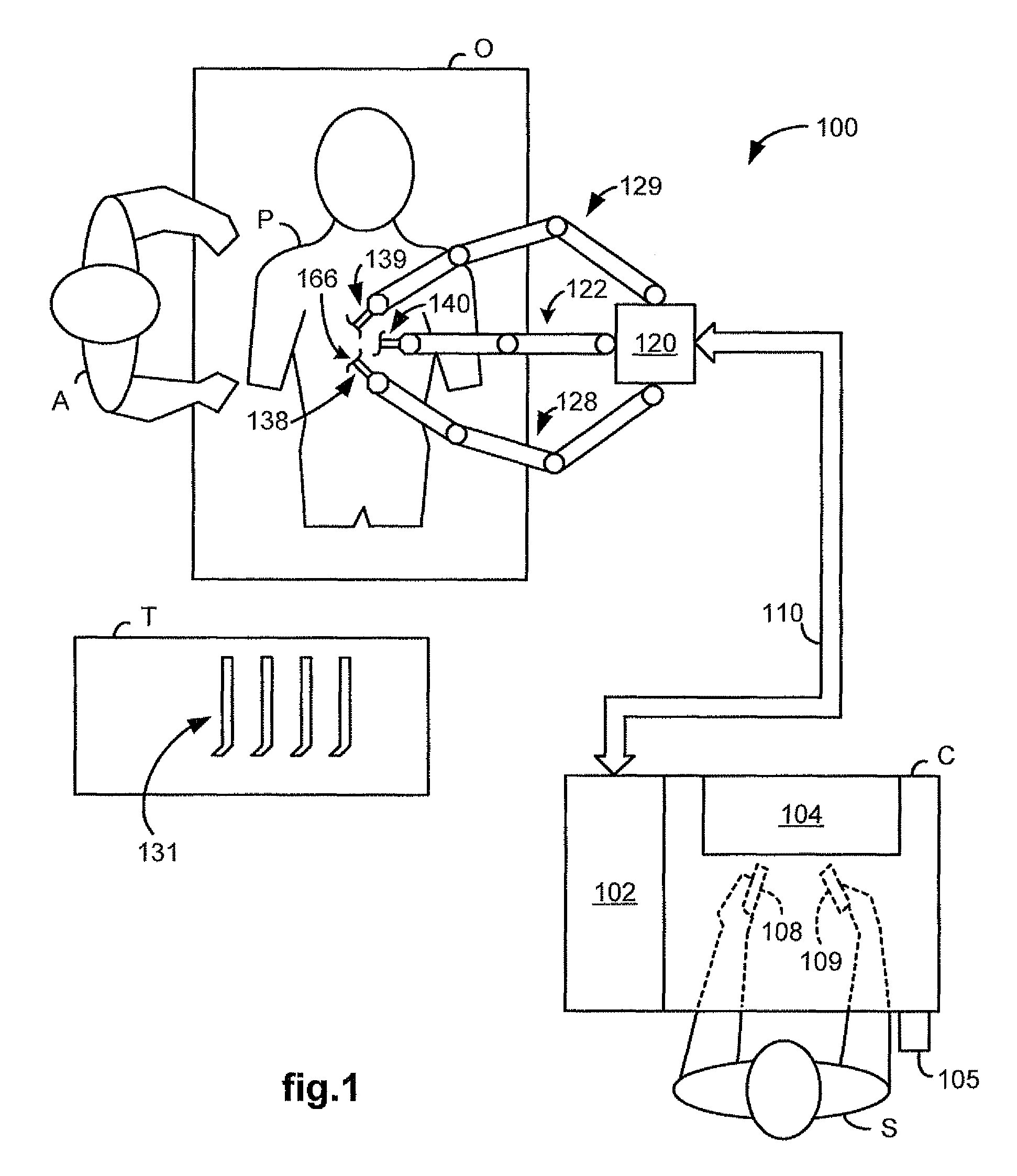
[0032]FIG. 1 illustrates, as an example, a top view of an operating room employing a medical robotic system. The medical robotic system in this case is a minimally invasive robotic surgical system 100 including a Console (“C”) utilized by a Surgeon (“S”) while performing a medical procedure, such as a diagnostic or surgical procedure, with assistance from one or more Assistants (“A”), on a Patient (“P”) who is reclining on an Operating table (“O”).

[0033]The Console includes a 3-D monitor 104 for displaying a 3-D image of a surgical site to the Surgeon, left and right manipulatable input devices 108, 109, a foot pedal 105, and a processor 102. The input devices 108, 109 may include any one or more of a variety of input devices such as joysticks, gloves, trigger-guns, hand-operated controllers, or the like. The processor 102 may be a dedicated computer integrated into the Console or positioned next or near to it, or it may be broken up into a number of processing or controller compone...


PUM


Abstract

A medical robotic system includes a surgical instrument, a robotic arm assembly, an input device, and a processor. The surgical instrument has an end effector and a sensor for sensing a force exerted by the end effector, and is operatively mounted on the robotic arm assembly. The processor is configured to receive commanded movement of the end effector from the input device, receive information of the force from the sensor, determine a reduced velocity of the commanded movement that would inhibit damage causing motion of the end effector, and control robotic manipulation of the surgical instrument in response to the commanded movement of the end effector while restricting the velocity of the commanded movement to the reduced velocity.

Description

FIELD OF THE INVENTION[0001]The present invention generally relates to medical robotic systems and in particular, to a medical robotic system adapted to inhibit motions resulting in excessive end effector forces.BACKGROUND OF THE INVENTION[0002]Medical robotic systems such as those used in performing minimally invasive surgical procedures offer many benefits over traditional open surgery techniques, including less pain, shorter hospital stays, quicker return to normal activities, minimal scarring, reduced recovery time, and less injury to tissue. Consequently, demand for minimally invasive surgery using such medical robotic systems is strong and growing.[0003]Examples of medical robotic systems include the da Vinci® Surgical System and the da Vinci® S™ Surgical System from Intuitive Surgical, Inc., of Sunnyvale, Calif. Each of these systems includes a surgeon's console, a patient-side cart, a high performance three-dimensional (“3-D”) vision system, and Intuitive Surgical's propriet...

Claims


Application Information

Patent Timeline
Patent Type & Authority Patents(United States)
IPC IPC(8): A61B17/00
CPCA61B19/2203A61B19/5212A61B2019/2223A61B2019/2234A61B2019/2242A61B2019/2292A61B2019/464A61B2090/064A61B34/71A61B90/361A61B34/30A61B34/37A61B2034/305A61B34/76
Inventor PRISCO, GIUSEPPE
Owner INTUITIVE SURGICAL OPERATIONS INC
Learn More