
Thin film transistor, manufacturing method thereof, and TFT LCD using the same

a technology of thin film transistors and liquid crystal displays, which is applied in the direction of electrical devices, semiconductor devices, instruments, etc., can solve the problems of flickering and mura, poor image quality phenomenon, etc., and achieve the effect of suppressing flickering and mura, reducing cgs, and increasing the w/l of the channel of a

Active Publication Date: 2010-11-09
BEIJING BOE OPTOELECTRONCIS TECH CO LTD +1
View PDF22 Cites 3 Cited by
  • Summary
  • Abstract
  • Description
  • Claims
  • Application Information

AI Technical Summary

Benefits of technology

The present invention aims to decrease the flickering and mura phenomena in the display quality of a TFT LCD by improving the channel profile of the TFT. This is achieved by changing the profile of the channel region between the source and drain electrodes in a bend line, which reduces the overlapping area between the gate and source electrodes and increases the width / length ratio of the channel. The method of forming the TFT includes forming a gate electrode over a substrate, forming a gate insulation layer over the gate electrode, forming an active layer having a source region, a drain region, and a channel region over the gate insulation layer, and patterning the source and drain electrodes. The invention can be applied to a sub-pixel structure of a TFT LCD, where the sub-pixel includes a pixel electrode and a TFT. The technical effect of the invention is to decrease the flickering and mura phenomena in the display quality of a TFT LCD.

Problems solved by technology

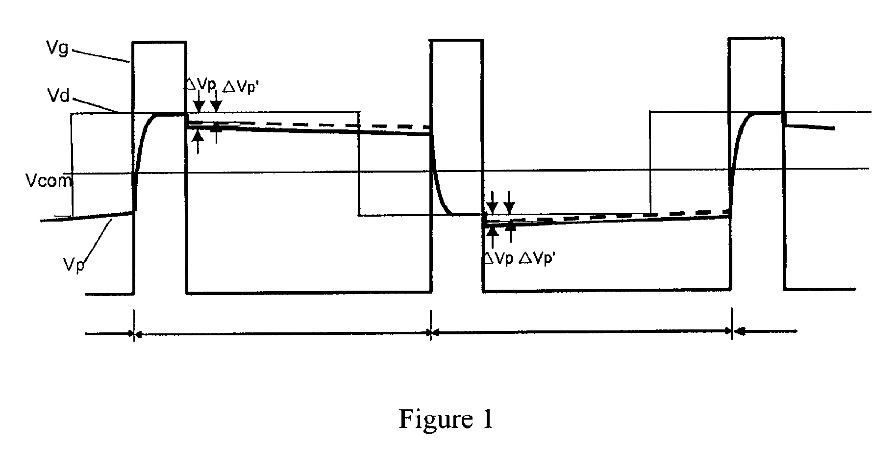
Flickering and Mura (a phenomenon of poor image quality) are two main defects among those that affect the image displaying quality of LCDs.
Furthermore, in the manufacture process, the actual values of a width / length ratio (W / L) of the channel in TFTs vary between different display areas due to the factors such as instability of process and apparatus, resulting in different degrees of charging for sub-pixels in different areas.

Method used


Image

  • Thin film transistor, manufacturing method thereof, and TFT LCD using the same
  • Thin film transistor, manufacturing method thereof, and TFT LCD using the same
  • Thin film transistor, manufacturing method thereof, and TFT LCD using the same

Examples


Embodiment Construction

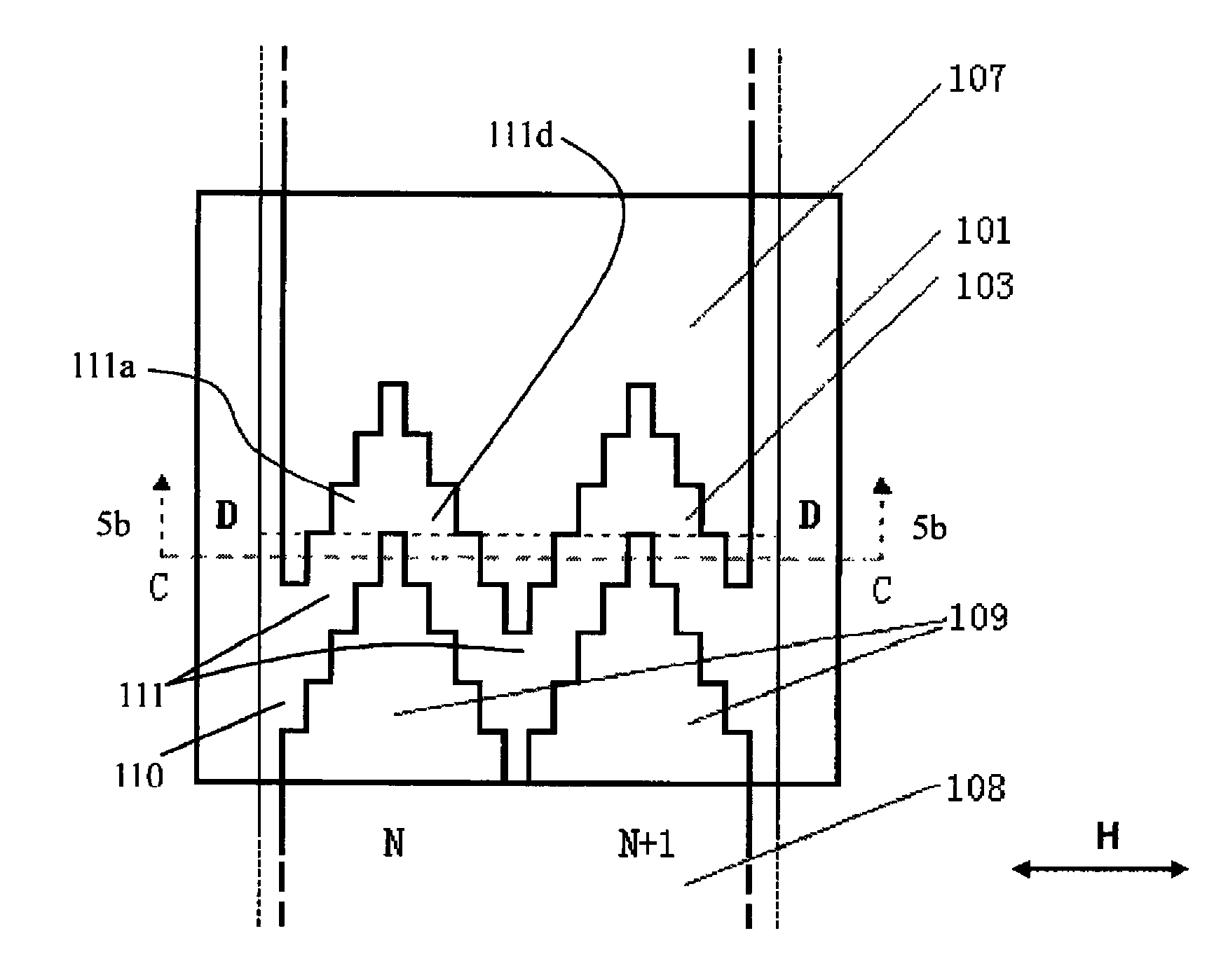
[0029]FIG. 5a is a plan view of the channel region of a TFT according to an embodiment of the present invention.

[0030]As shown in FIG. 5a, an active layer 103 having a source region, a drain region and a channel region therebetween is formed on a gate electrode 101. A drain electrode 107 and a source electrode 108 are formed over the active layer 103 in the source and drain region on the opposite sides of the channel region, respectively. The edge of an overlapping area 109 between the source electrode 108 and the gate electrode 101 (i.e., the edge of the source electrode opposite to the drain electrode) is changed in a bend line as a whole so as to assume a curved or angular shape. That is, the general profile of the channel region is changed in a non-linear manner and has undulation(s), and the bend line for example can assume various shapes such as zigzag, wave, and the like. The zigzag or wave can have one or more peaks (undulations), and if there are a plurality of peaks, the p...


PUM


Abstract

A thin film transistor (TFT) that comprises a gate electrode on a substrate, a gate insulation layer on the gate electrode, an active layer having a source region, a drain region, and a channel region on the gate insulation layer, and a source electrode and a drain electrode formed over the source region and drain region of the active layer respectively and facing each other with respect to the channel region. The profile of channel region between the source electrode and drain electrode is changed in a bend line. A method for forming the TFT is also provided.

Description

FIELD OF THE INVENTION[0001]The present invention relates to a thin film transistor (TFT), the manufacturing method thereof, and a TFT liquid crystal display (TFT LCD) using the same.BACKGROUND OF THE INVENTION[0002]Liquid crystal display (LCD) techniques have being developed rapidly in the last decade with a great advance from the screen size to the display quality. The performances of LCDs have reached those of conventional cathode ray tubes (CRTs) in all respects with the continuous efforts, thus LCDs take a leading role as a substitute for CRTs.[0003]As the production of LCDs increases, the intense competitions among manufacturers enable the enhancement of the product performances, with a focus on improving of the image quality of LCDs. Flickering and Mura (a phenomenon of poor image quality) are two main defects among those that affect the image displaying quality of LCDs. As well known, a TFT LCD displays a complete and accurate image by controlling a voltage applied on each o...

Claims


Application Information

Patent Timeline
Patent Type & Authority Patents(United States)
IPC IPC(8): H01L29/04
CPCH01L27/12H01L29/41733H01L29/78696G02F1/1368H01L27/124
Inventor WANG, WEIWU, HONGJIANGLONG, CHUNPINGLEE, CHANG HEE
Owner BEIJING BOE OPTOELECTRONCIS TECH CO LTD
Learn More